A vibrating trough lifting and moving device

A technology of moving device and vibrating slot, applied in the direction of lifting device, etc., can solve the problems of affecting the running performance of vibration slot, inconvenient removal, deformation of vibration slot balance body, etc., to achieve convenient and fast removal process, ensure appearance integrity, and eliminate vibration slot. The effect of the possibility of balancing

Active Publication Date: 2017-11-17
HUBEI CHINA TOBACCO IND
View PDF5 Cites 0 Cited by
  • Summary
  • Abstract
  • Description
  • Claims
  • Application Information

AI Technical Summary

Problems solved by technology

[0004] Due to the limitation of the field equipment layout, and the length of the vibration tank is generally long, it is very inconvenient to remove, and in the process of horizontally moving the vibration tank by the hydraulic trolley, its padding of the load-bearing part may also cause the deformation of the balance body of the vibration tank, affecting the vibration tank running performance

Method used


Image

  • A vibrating trough lifting and moving device

Examples


Embodiment Construction

[0011] The technical solutions in the present invention will be clearly and completely described below in conjunction with the accompanying drawings in the present invention.

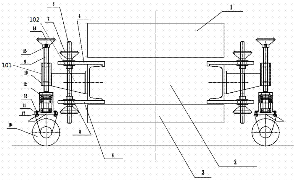
[0012] figure 1 Shown is a structural diagram of the vibrating trough lifting and moving device of the present invention. The vibrating trough lifting and moving device is used to be installed on the left, right, front and rear parts of the vibrating tank, including a locking part, a lifting part, and a roller moving part.

[0013] The locking part includes an upper splint 4, a lower splint 5, a clamping screw 6, a first circular handle 7, and an adjustment nut 8. The clamping screw 6 passes through the upper splint 4 and the lower splint 5 from top to bottom in turn, and the clamping screw The upper end and the lower end of 6 are respectively provided with a first circular handle 7 and an adjusting nut 8 . After the upper splint 4 and the lower splint 5 clamp the frame 2 of the tank body, rotate the u...


PUM


Abstract

The invention provides a vibration groove lifting and moving device. The vibration groove lifting and moving device is mounted on the left, the right, the front and the rear portions of a vibration groove and comprises a locking part, a lifting part and a wheel moving part. The locking part comprises an upper clamp plate and a lower clamp plate used for clamping a frame of the groove, clamping screws sequentially penetrate the upper clamp plate and the lower clamp plate from top to bottom, and the upper ends and the lower ends of the clamping screws are provided with first circular handles and adjusting nuts respectively; the lifting part comprises bases, bearings mounted on the base and lifting screws connected with the bearings, second circular handles are arranged at the tops of the lifting screws, locking pins are mounted on the lower portions of the second circular handles, and the lifting screws are fixedly connected by lifting blocks; the wheel part comprises wheel carriers connected at the bottoms of the bases and wheels mounted on the wheel carriers. By means of the vibration groove lifting and moving device, the vibration groove can be conveniently moved out, moving process is convenient and quick, and a vibration groove balance is not damaged.

Description

technical field [0001] The invention relates to the technical field of cigarette equipment, in particular to a vibration tank lifting and moving device. Background technique [0002] The vibrating trough is one of the common attached equipment in the silk production line. It is often used in occasions where materials need to be loosened by using its vibration conveying characteristics. The transmission device of the vibrating trough is generally arranged under the trough body. When the transmission is overhauled, the maintenance personnel need to work under the vibrating trough. [0003] However, at the outlet vibration groove of the wire cutter, because the outlet of the wire cutter is low and there is a hopper between them, the height of the outlet vibration groove of the wire cutter is relatively low, and the transmission device is only about 150-300mm from the ground. , During inspection and maintenance work, first use a hydraulic trolley to raise the vibrating trough (...

Claims


Application Information

Patent Timeline
Patent Type & Authority Patents(China)
IPC IPC(8): B66F3/08B66F3/46
CPCB66F3/08B66F3/46B66F2700/04
Inventor 王志强黎伟雄
Owner HUBEI CHINA TOBACCO IND
Why Eureka
Try Eureka