An Underwater Target Location Method Based on Improved Frequency Difference of Arrival

A positioning method and underwater target technology, which is applied in the field of underwater target positioning based on improved arrival frequency difference, can solve the problems of low signal frequency resolution and inability to accurately measure target azimuth, so as to improve positioning accuracy and reduce design difficulty Effect

Active Publication Date: 2022-06-03
HARBIN ENG UNIV
View PDF14 Cites 0 Cited by
  • Summary
  • Abstract
  • Description
  • Claims
  • Application Information

AI Technical Summary

Problems solved by technology

For underwater target detection, since the speed of the underwater vehicle and the signal carrier frequency are much lower than satellite and radio detection, and the underwater environment is harsh, the frequency resolution of the signal is low, and the target orientation cannot be accurately measured. The traditional FDOA method Not suitable for underwater environment

Method used


Image

  • An Underwater Target Location Method Based on Improved Frequency Difference of Arrival
  • An Underwater Target Location Method Based on Improved Frequency Difference of Arrival
  • An Underwater Target Location Method Based on Improved Frequency Difference of Arrival

Examples


Embodiment 1

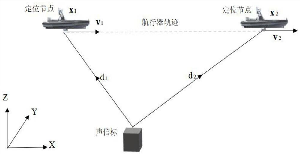
[0052] The underwater target localization method based on the improved arrival frequency difference refers to the Doppler frequency shift of the arrival signal due to the relative motion between the target and the underwater mobile platform. The technique of the location of the target. Its scene situation diagram is as follows figure 1As shown, the location of the underwater acoustic beacon is determined primarily by a single maneuvering vehicle receiving the signals transmitted by the acoustic beacon at two locations. In the figure, the aircraft travels along the preset route at a certain speed, and the acoustic beacon emits acoustic pulse signals at a certain period. 1 , x 2 The location (locating node) receives the ping signal. The underwater target location method based on the improved arrival frequency difference has a wide range of application prospects. Reconnaissance, search and interception of enemy underwater targets.

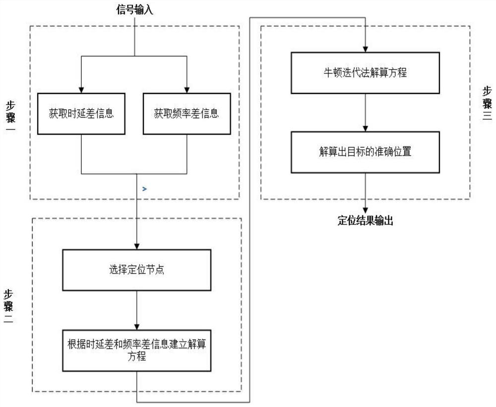
[0053] A method for locating an underwater...

Embodiment 2

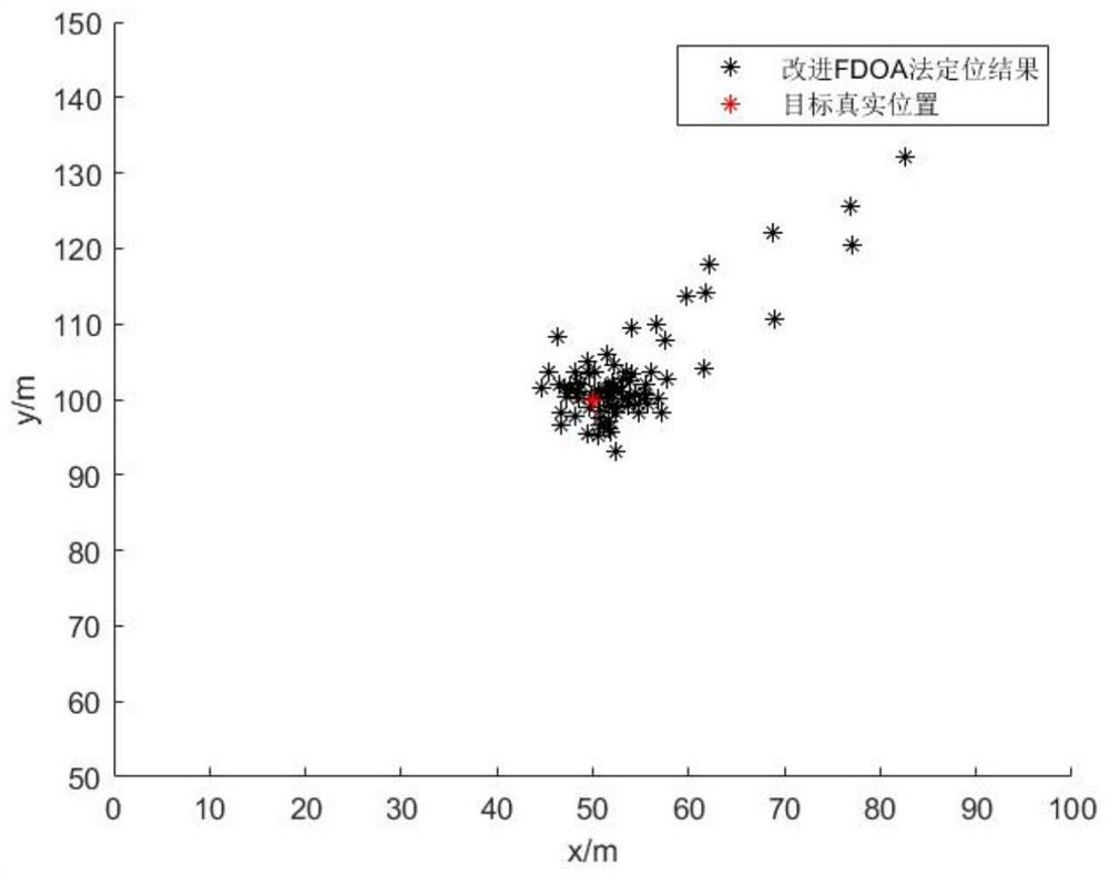
[0094] The simulation parameters are as follows: without loss of generality, the coordinates of the target are set to x t =[0,200,50], the track of the motorized positioning platform is a straight track, the depth is 0m, the motorized positioning platform moves at a uniform speed, and the speed is 5m / s. The estimation error of each input parameter is: the measurement error of frequency difference information is 0.5Hz, the measurement error of time delay difference information is 1ms, the measurement error of sound speed is 2m / s, the coordinate error of positioning node is 1.5m, and the speed measurement error of motorized positioning platform is 1%. Other parameters are set as follows: the speed of sound is 1500m / s, the frequency of the acoustic beacon signal is 10kHz, and the signal period is 1s.

[0095] The positioning method involved in the present invention is used to estimate the position of the acoustic beacon. The real-time solution results are as image 3 As shown,...


PUM


Abstract

The invention discloses an underwater target positioning method based on the improved arrival frequency difference. Step 1: Obtain the time delay difference information and frequency difference information required for the calculation from the input signal; Step 2: Establish the solution equation of the target position according to the obtained time delay difference and frequency difference information; according to the obtained information, establish the underwater The time delay difference relation equation and the frequency difference relation equation between the maneuvering platform and the target at two different positions form a positioning solution equation group; Step 3: Use the Newton iteration method to solve the equation, if the obtained result does not meet the iteration accuracy Requirements, and then repeat the cyclical solution until it meets the accuracy requirements of the solution, and finally complete the precise positioning solution. The invention improves the traditional frequency difference satellite positioning method so that it can be applied to the occasion of underwater acoustic positioning, effectively improves the positioning accuracy of the underwater acoustic positioning system and reduces the difficulty of software and hardware design.

Description

technical field [0001] The invention belongs to the field of underwater target positioning, and in particular relates to an underwater target positioning method based on improved arrival frequency difference. Background technique [0002] For Frequency Difference of Arrival (FDOA), it is mostly used in the field of satellite and radio positioning. Due to the relative motion between the radiation source and multiple stations, the arriving signal produces a Doppler frequency shift. By measuring the distance between different receiving stations The frequency difference of the arrival signal is obtained, and then the position information of the target itself is solved. For underwater target detection, because the speed and signal carrier frequency of underwater vehicles are much lower than satellite and radio detection, and the underwater environment is harsh, the frequency resolution of the signal is low, and it is impossible to accurately measure the target azimuth. The tradit...

Claims


Application Information

Patent Timeline
Patent Type & Authority Patents(China)
IPC IPC(8): G01S5/18
CPCY02D30/70
Inventor 孙思博梁国龙明瑞和曲龙付进王燕王逸林张光普齐滨邹男
Owner HARBIN ENG UNIV
Why Eureka
Try Eureka