
Load sensor fast to install and using method thereof

A load sensor, fast technology, applied in the field of communication, can solve problems such as single detection data, difficult to work effectively, unable to be affected by heavy objects and effective detection of gravity

Active Publication Date: 2021-04-23
NANJING TOP SUN TECH
View PDF6 Cites 0 Cited by
  • Summary
  • Abstract
  • Description
  • Claims
  • Application Information

AI Technical Summary

Problems solved by technology

Although it can meet the needs of use to a certain extent, these traditional load cells currently used often have fixed equipment structures and single detection data. The impact of the installation and positioning results in low efficiency and poor installation and positioning stability; on the other hand, it often only meets the detection of the force in the vertical direction during the detection operation, and cannot detect the impact of heavy objects on the structure of the bearing equipment and the gravitational force. Effective detection, so the traditional load cells currently used have poor installation positioning stability and reliability to varying degrees, low efficiency in installation and maintenance operations, and also lead to relatively poor detection accuracy, which is difficult to effectively meet the needs of effective work

Method used


Image

  • Load sensor fast to install and using method thereof
  • Load sensor fast to install and using method thereof
  • Load sensor fast to install and using method thereof

Examples


Embodiment Construction

[0021] In order to facilitate the implementation of the technical means, creative features, goals and effects achieved by the present invention, the present invention will be further elaborated below in conjunction with specific embodiments.

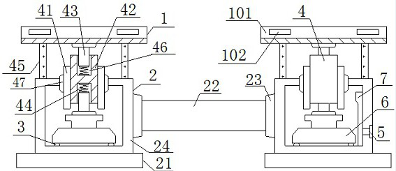
[0022] Such as figure 1 and 2 A fast-installed load sensor is shown, including a connecting cutting board 1, a load-bearing keel 2, a guide rail 3, a load-bearing column 4, a terminal 5, a load sensor 6, and a drive circuit 7, wherein the load-bearing keel 2 is rectangular in cross section. Columnar frame structure, its upper end surface is connected with at least one connecting cutting board 1 through the bearing column 4, the lower end surface and the upper end surface of the connecting cutting board 1 are distributed parallel to the axis of the bearing keel 2, and the number of load sensors 6 is connected to the upper end surface of the bearing keel 2 The number of connecting chopping boards 1 is the same, and each load sensor 6 is e...


PUM


Abstract

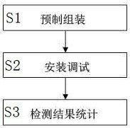
The invention relates to a load sensor fast to install and a using method thereof. The load sensor comprises a connecting cutting board, bearing keels, guide sliding rails, bearing columns, wiring terminals, load sensors and a driving circuit, the upper end faces of the bearing keels are connected with the connecting cutting board through the bearing columns, and the load sensors are embedded in the bearing keels; the upper end face of the load sensor is connected with the lower end face of the connecting chopping board through at least one bearing column, the wiring terminal is embedded in the outer surface of the bearing keel and electrically connected with the drive circuit, and the drive circuit is embedded in the lower end face of the bearing keel. The using method comprises the three steps of prefabricating and assembling, mounting and debugging and detection result statistics. On one hand, the universality is good, and the requirements of matched use operation of various different bearing devices can be effectively met; and on the other hand, the detection precision and the comprehensiveness of detection data acquisition can be greatly improved while accurate detection operation is carried out on the loaded heavy object in operation.

Description

technical field [0001] The invention relates to a quickly installed load sensor and a method for using the same, belonging to the technical field of communication. Background technique [0002] At present, load sensors are required to accurately collect and monitor the quality of heavy objects in load-carrying vehicles and other transportation tools and weighing equipment. To meet this need, a variety of load sensor devices have been developed, such as the patent publication number CN212206319U, The publication date is 20201222, the patent application number is 202020547998.8, and the patent name is a wireless load sensor; the patent publication number is CN208860456U, the publication date is 20190514, the patent application number is 201821785906.9, and the patent name is a technical activity such as a vehicle load sensor. product. Although it can meet the needs of use to a certain extent, these traditional load cells currently used often have fixed equipment structures an...

Claims


Application Information

Patent Timeline
IPC IPC(8): G01G19/02
CPCG01G19/02
Inventor 田海霞
Owner NANJING TOP SUN TECH
Learn More