Method and application for determining curve corner and deflection direction of road design curve

A deflection direction and road design technology, applied in special data processing applications, geometric CAD and other directions, can solve the problems of complicated calculation and deflection direction judgment, and achieve the effect of simple and clear calculation method, easy operation, and simplified judgment steps.

Active Publication Date: 2021-09-21
CHINA RAILWAY NO 2 ENG GRP CO LTD +1
View PDF5 Cites 0 Cited by
  • Summary
  • Abstract
  • Description
  • Claims
  • Application Information

AI Technical Summary

Problems solved by technology

[0007] The purpose of the present invention is to overcome the complicated problem of calculating the curve angle and judging the deflection direction of the line engineering plane in the prior art, and to provide a method for determining the curve angle and deflection direction of the road design curve

Method used


Image

  • Method and application for determining curve corner and deflection direction of road design curve
  • Method and application for determining curve corner and deflection direction of road design curve
  • Method and application for determining curve corner and deflection direction of road design curve

Examples


Embodiment 1

[0060] The design and construction of railway and highway engineering line planes involve a large number of curve angle calculations and curve deflection direction judgments. However, the existing intersection method for calculating curve angles and judging curve deflection directions is cumbersome and complicated, which has led to serious problems in engineering line plane design. The steps are cumbersome, so it is necessary to develop a simpler method for calculating the curve rotation angle and determining the deflection direction of the curve.

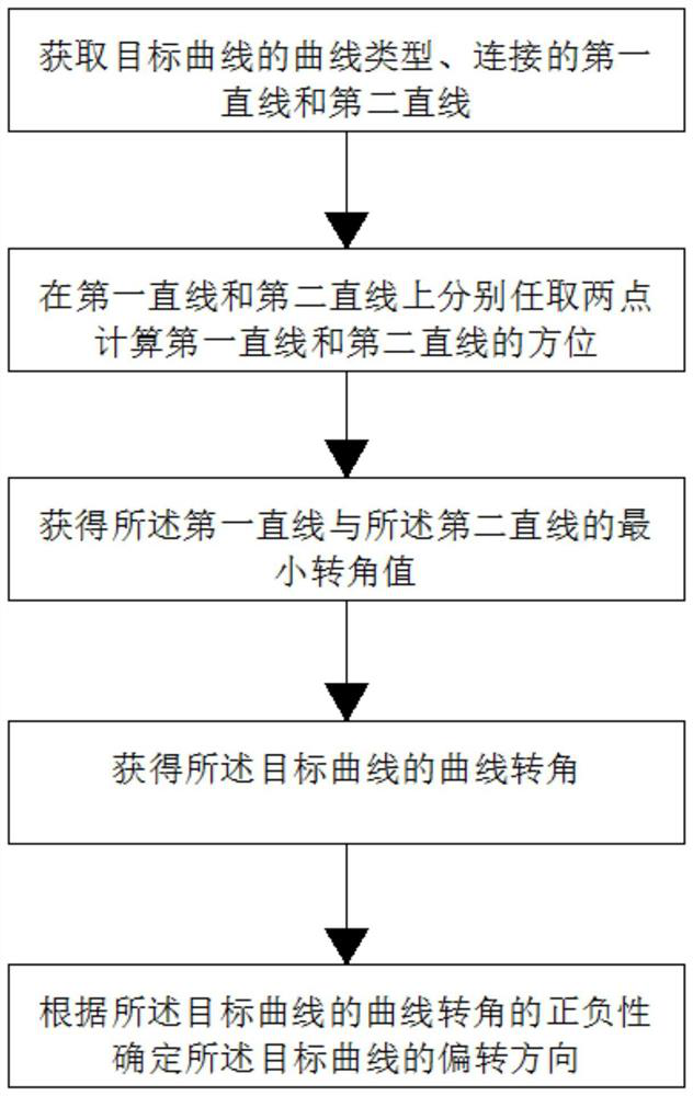
[0061] In order to solve the above technical problems, the inventor proposed a method for determining the curve corner and deflection direction of the road design curve in this application, see figure 1 , including the following steps:

[0062] S1: Obtain the curve type of the target curve and the first straight line and the second straight line respectively connecting the two ends of the target curve according to the road graphic ...

Embodiment 2

[0125] The application also discloses that the method for determining the curve angle and deflection direction of the road design curve is applied to the stakeout by the polar coordinate method of the total station engineering survey, and is used to calculate the size of the stakeout angle in polar coordinates and determine the deflection direction of the stakeout angle.

[0126] Said application includes the following steps:

[0127] refer to Figure 5 , establish a coordinate system, and determine the coordinates of the mirror point, backsight point, and stakeout point in this coordinate system, determine the first straight line with the mirror point and backsight point of the total station, and its azimuth points to the direction of the backsight point; The mirror point of the instrument and the stakeout point determine the second straight line, and its azimuth points to the direction of the stakeout point; the mirror point of the total station is the intersection of the fi...


PUM


Abstract

The invention discloses a method for determining the curve angle and deflection direction of a road design curve and its application, and relates to the technical field of road plane alignment design and construction, including: obtaining the curve type of the target curve, and the first method for connecting the two ends of the target curve respectively. a straight line and a second straight line; two points are randomly selected on the first straight line and the second straight line respectively, and the azimuth of the first straight line and the second straight line are calculated; the azimuth deflection of the first straight line is obtained to the The minimum rotation angle value of the orientation of the second straight line; the curve rotation angle and deflection direction of the target curve are obtained according to the type of the target curve and the minimum rotation angle value. The invention also discloses the application of the method in engineering survey by using the total station. The calculation method of the present invention is simple and clear, and only needs to determine whether the target curve is a general curve or a reverse curve in the calculation process, and the calculation of the curve corner value and the deflection direction do not require any judgment steps.

Description

technical field [0001] The invention relates to the technical field of road plane alignment design and construction, in particular to a method for determining the curve corner and deflection direction of a road design curve and its application. Background technique [0002] The planes of traffic engineering lines such as railways and highways are composed of straight lines and curves. Among them, the curves include circular curves and transitional curves, and the transitional curves are divided into clothoids and cubic parabolas. The basic structural form of a complete line plane curve is straight line + transitional curve + circular curve + transitional curve + straight line. Its combined transformation forms include: straight line + circular curve + straight line form, straight line + transitional curve + circular curve + straight line form, straight line + circular curve + transitional curve + straight line form, etc. Regardless of the type of plane curve, once the two ...

Claims


Application Information

Patent Timeline
Patent Type & Authority Patents(China)
IPC IPC(8): G06F30/13
CPCG06F30/13
Inventor 杨维裕
Owner CHINA RAILWAY NO 2 ENG GRP CO LTD
Why Eureka
Try Eureka