A metallized film capacitor material tray locking mechanism

A technology of metallized film and locking mechanism, applied in capacitors, capacitor manufacturing, circuits, etc., can solve the problem of time-consuming disassembly and replacement of material trays, and achieve the effect of saving time

Active Publication Date: 2022-06-03
佛山市品尔电子有限公司
View PDF0 Cites 0 Cited by
  • Summary
  • Abstract
  • Description
  • Claims
  • Application Information

AI Technical Summary

Problems solved by technology

[0009] The object of the present invention is to provide a metallized film capacitor tray locking mechanism to solve the time-consuming problem of disassembling and replacing the tray in the above-mentioned background technology

Method used


Image

  • A metallized film capacitor material tray locking mechanism
  • A metallized film capacitor material tray locking mechanism
  • A metallized film capacitor material tray locking mechanism

Examples


Embodiment 1

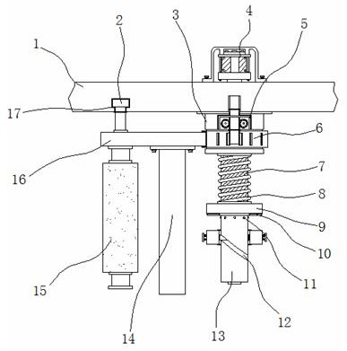
[0035] Example 1: See Figure 1-6 , a metallized film capacitor tray locking mechanism, comprising a main board 1, a base 3, a turntable 6 and a rod body 13, one side of the bottom end of the main board 1 is fixedly connected with a base 3, and the bottom end of the base 3 is movably connected with a turntable 6, the base One end between 3 and the turntable 6 is provided with a fixed structure 5, one side of the turntable 6 is fixedly connected with a connection plate 16, and a cleaning structure 14 is arranged at the middle position of the bottom end of the connection plate 16, and one side of the bottom end of the connection plate 16 is movable. The roller 15 is connected, one side of the top of the connecting plate 16 is fixedly connected with the insertion rod 2, the other side of the bottom of the main board 1 is provided with a limit groove 17, the inside of the base 3 is movably connected with a rod body 13, and the inside of the rod body 13 is provided with a lubricatin...

Embodiment 2

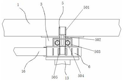
[0038] Embodiment 2: The fixed structure 5 is composed of a storage slot 501, a rack bar 502, a housing 503, a gear 504 and a block 505. The housing 503 is fixedly connected to the top of the base 3, and the two sides inside the housing 503 are respectively flexibly connected. There is a gear 504, a rack bar 502 is provided in the middle of the housing 503, a storage slot 501 is provided on one side of the bottom end of the main board 1, and blocks 505 are respectively fixedly connected to the top of the turntable 6

[0039] The gear 504 is distributed symmetrically about the vertical midline of the rack bar 502;

[0040] Specifically, such as figure 1 and figure 2 As shown, pull the roller 15 to the appropriate position with the connecting plate 16, then pinch the protrusion on the rack bar 502 and insert it between the ancient blocks 505 of the turntable 6, at this time, two The position of the rack bar 502 is tightened under the meshing limit of the side gear 504, so as ...

Embodiment 3

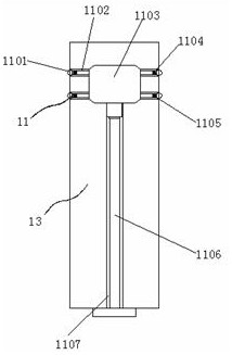
[0041] Embodiment 3: The lubricating structure 11 is composed of a sliding ball 1101, a flow channel 1102, a main chamber 1103, a cotton pad 1104, an active groove 1105, a push rod 1106 and a drainage groove 1107. The drainage groove 1107 is arranged at the bottom end of the rod body 13, The inside of the drainage groove 1107 is movably connected with a push rod 1106. The top of the drainage groove 1107 is provided with a main chamber 1103, and the two sides and two ends of the main chamber 1103 are respectively provided with multiple groups of flow channels 1102. One side of the flow channel 1102 There is also a movable groove 1105, and the inside of the movable groove 1105 is movably connected with a sliding ball 1101, and the inside of one side of the flow channel 1102 is fixedly connected with a cotton pad 1104;

[0042] The sliding bead 1101 is arranged inside the movable groove 1105, and the sliding bead 1101, the movable groove 1105 and the rod body 13 are arranged in co...


PUM


Abstract

The invention discloses a metallized film capacitor tray locking mechanism, specifically relates to the technical field of capacitor production equipment, comprising a main board, a base, a turntable and a rod body, one side of the bottom end of the main board is fixedly connected with a base, and the bottom end of the base is movable A turntable is connected, one end between the base and the turntable is provided with a fixed structure, one side of the turntable is fixedly connected with a connection plate, and a cleaning structure is provided at the middle of the bottom end of the connection plate, and the bottom end of the connection plate One side is movably connected with a roller. In the present invention, a fixed structure is provided at one end between the base and the turntable, and the roller is shifted to a suitable position with the connecting plate, and then the protrusion on the rack bar is pinched and inserted between the ancient blocks of the turntable. The position of the rack bar can be tightened under the meshing limit of the gears on both sides inside the housing, so as to adjust the height of the guide roller to increase or decrease the tension on the metal film as needed to ensure its smooth export.

Description

technical field [0001] The invention relates to the technical field of capacitor production equipment, in particular to a metallized film capacitor tray locking mechanism. Background technique [0002] A capacitor is a combined conductor used to store a small amount of charge. It is used in a wide range of fields. It can be found in various electrical appliances ranging from computers and televisions to small mobile phones and walkmans. In production and processing, its The internal electrodes are often made of metallized film as a raw material and are manufactured in a multi-layer winding manner. Therefore, multiple roller shafts that fix the film tray are required to limit it. Sometimes it is inconvenient and the functionality is relatively single, and it is easy to reduce the efficiency of production and processing. [0003] In the process of realizing the present invention, the inventors have found that at least the following problems in the prior art have not been reso...

Claims


Application Information

Patent Timeline
Patent Type & Authority Patents(China)
IPC IPC(8): H01G13/00
CPCH01G13/00Y02P70/10
Inventor 罗通徐亚萍
Owner 佛山市品尔电子有限公司
Why Eureka
Try Eureka