

Iron rod bending machine for building construction
A technology of building construction and bending mechanism, which is applied in the direction of manufacturing tools, metal processing equipment, feeding devices, etc., and can solve the problems of long time consumption, difficult work coefficient, and iron rod bending, etc.
- Summary
- Abstract
- Description
- Claims
- Application Information
AI Technical Summary
Problems solved by technology
Method used
Image

Examples
Embodiment 1
[0071] A kind of iron rod bending machine for building construction, such as figure 1 As shown, it includes a base 1, a support column 2, a working plate 3 and a bending mechanism 4. The front middle of the base 1 is provided with a support column 2, the top of the support column 2 is provided with a working plate 3, and the top of the working plate 3 is provided with a bending mechanism. Institution 4.
[0072] When people need to bend iron rods, they can use an iron rod bending machine for building construction. First, the user places the iron rod in the middle of the working plate 3, and bends the iron rod through the bending mechanism 4 to realize the bending effect.
Embodiment 2
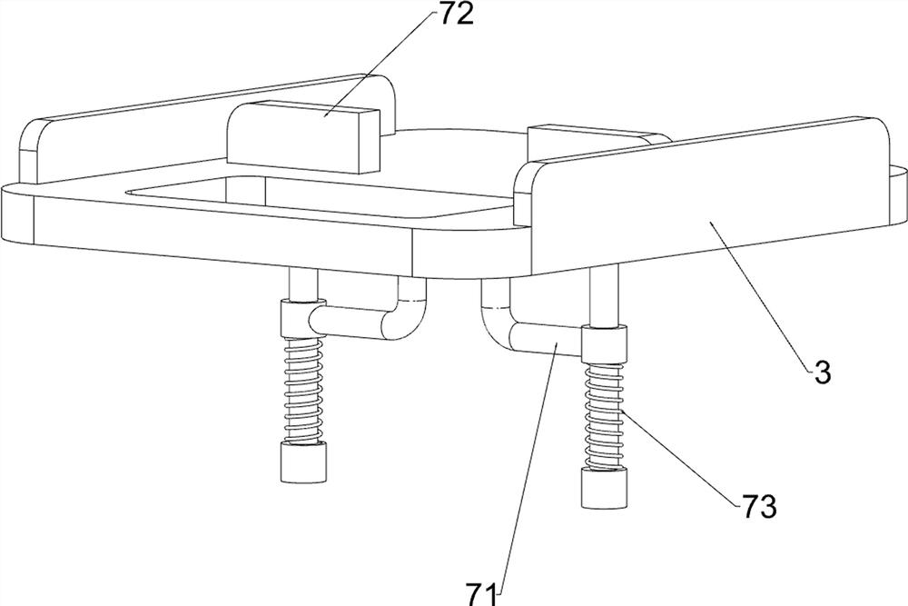
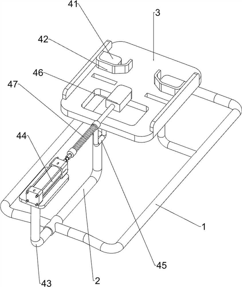
[0074] On the basis of Example 1, such as figure 2 As shown, the bending mechanism 4 includes a bending top block 41, a slidable fixed block 42, a first support rod 43, a cylinder 44, a first sliding sleeve 45, a bending top plate 46 and a first spring 47, and the top of the working plate 3 The rear side is provided with a bending top block 41, and the middle part of the front side of the two bending top blocks 41 is provided with a slidable fixed block 42. The base 1 is provided with a first support rod 43, and the first support rod 43 and the support column 2 connection, a cylinder 44 is installed on the top of the first support rod 43, a bent top plate 46 is provided in the middle of the rear side of the cylinder 44, a first sliding sleeve 45 is provided at the bottom of the working plate 3, and the bending top plate 46 is slidably connected with the first sliding sleeve 45 , A first spring 47 is wound on the bent top plate 46 .
[0075] The user opens the cylinder 44, an...
Embodiment 3
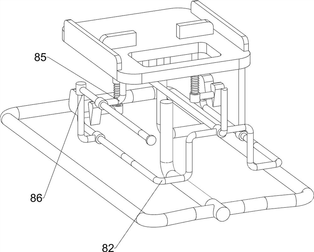
[0077] On the basis of Example 2, such as Figure 3 to Figure 10 As shown, a discharge mechanism 5 is also included. The top of the working plate 3 is provided with a discharge mechanism 5. The discharge mechanism 5 includes a second sliding sleeve 51, a third sliding sleeve 52, a first driving rod 53, a first connecting rod 54. The second driving rod 55, the second spring 56, the second connecting rod 57, the fourth sliding sleeve 58 and the third spring 59, the second sliding sleeve 51 is arranged in the middle of the bottom of the working plate 3, and the middle part of the rear side of the working plate 3 is A third sliding sleeve 52 is provided, and a first driving rod 53 is provided at the bottom of the second sliding sleeve 51, and the first driving rod 53 is slidably connected with the second sliding sleeve 51. Two connecting rods 57, the rear ends of the two second connecting rods 57 are provided with the fourth sliding sleeve 58, the first connecting rod 54 is arrang...
PUM
 Abstract
Description
Claims
Application Information