Positioning structure of embedded hardware in injection molding die

A technology of injection molding and positioning structure, applied in the field of injection molding, can solve the problems of limited function of hardware, offset, movement, and product size difference of hardware

Pending Publication Date: 2021-04-27
惠州市凯中精密技术有限公司
View PDF11 Cites 2 Cited by
  • Summary
  • Abstract
  • Description
  • Claims
  • Application Information

AI Technical Summary

Problems solved by technology

[0007] Therefore, the technical problem solved by the present invention is that in the prior art, fixing the entire hardware as an insert by fixing the hardware connector during injection molding has limited effect, and it cannot be avoided that the hardware will be biased and moved by the injection material, resulting in The problem of product size out of tolerance

Method used


Image

  • Positioning structure of embedded hardware in injection molding die
  • Positioning structure of embedded hardware in injection molding die
  • Positioning structure of embedded hardware in injection molding die

Examples


Embodiment Construction

[0039] The technical solutions of the present invention will be clearly and completely described below in conjunction with the accompanying drawings.

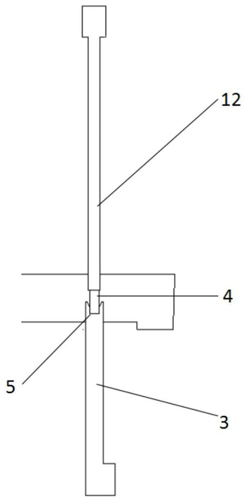
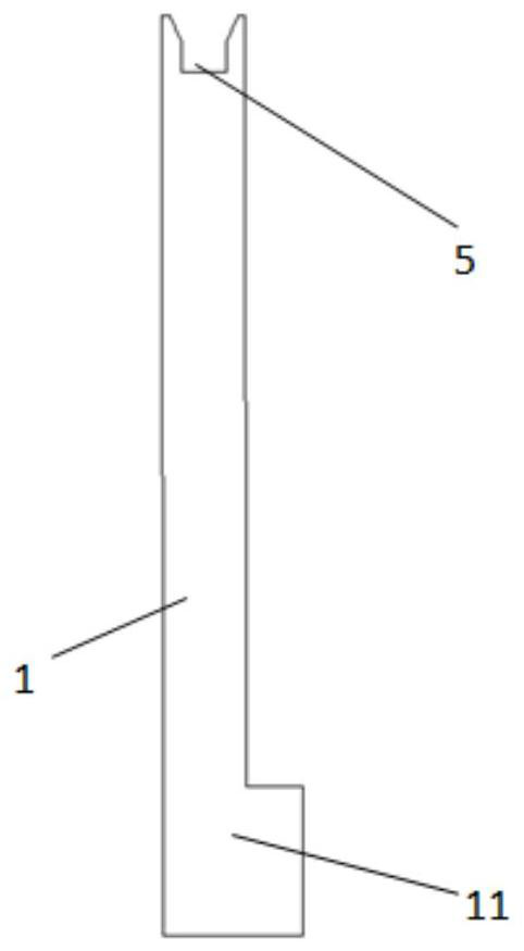
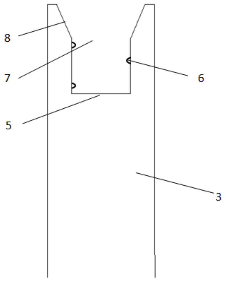
[0040] see figure 1 , the positioning structure of the inlaid hardware in the injection molding mold of the present invention includes a plurality of positioning parts composed of insert pins 12 and inserts 3, and one end of each positioning part is a fixed end 1 fixedly connected with the mold body of the mold , and the other end is the positioning end that is in contact with the hardware set in the mold cavity 2 of the mould. When the fixed end 1 fixes the positioning member to the core of the mold, the positioning end extends into the mold cavity 2 . In this embodiment, each hardware piece is equipped with one setting pin 12 and one setting piece 3 . The fixed end 1 of the insert pin 12 is fixed to the front mold core 14 of the mould, and the fixed end 1 of the insert 3 is fixed to the rear mold core 13 of the mould. Wher...


PUM


Abstract

The invention discloses a positioning structure of an embedded hardware in an injection molding die. The positioning structure comprises a plurality of positioning pieces, wherein the positioning pieces are provided with fixed ends suitable for being fixed to a die body of the die and positioning ends extending into a die cavity when the fixed ends are fixed on the die body of the die; at least one positioning piece is an insert; and a positioning groove suitable for embedding of the embedded hardware is arranged in the positioning end of the insert. According to the positioning structure of the embedded hardware in the injection molding die, the mounting difficulty of the hardware is low, the time for mounting the hardware into the mold is short, the labor cost is saved, and the problems that the effect of fixing the whole hardware serving as the insert in a hardware connecting piece fixing mode during injection molding is limited, the hardware is punched to deviate and move by injection molding materials, and the product size is out of tolerance in the prior art can be effectively solved.

Description

technical field [0001] The invention relates to the field of injection molding, in particular to a positioning structure for inserting hardware in an injection molding mold. Background technique [0002] The connector is to build a communication bridge between the blocked or isolated circuits in the circuit, so that the current / signal can flow, and the circuit can realize the predetermined function. The connector for automobile engine is the core part of automobile engine, which is mainly composed of hardware and plastic. Part of the connector hardware is designed to be inside the plastic, and the other part is exposed for connecting wires. The plastic is used to fix the cladding hardware, arrange the hardware according to the required position and spacing, and insulate the hardware. [0003] When the connector is made, the hardware is placed as an insert into the mold cavity formed by the front and rear mold cores, and then injection molding is performed by injecting plas...

Claims


Application Information

Patent Timeline
Patent Type & Authority Applications(China)
IPC IPC(8): B29C45/14B29C33/12
CPCB29C45/14008B29C45/14065B29C33/12
Inventor 叶志强
Owner 惠州市凯中精密技术有限公司
Why Eureka
Try Eureka