
Intelligent logistics storage equipment

A technology of intelligent logistics and equipment, applied in the direction of conveyor objects, conveyors, storage devices, etc., can solve the problem of slow storage of logistics packages

Inactive Publication Date: 2021-04-30
谢剑嘉
View PDF9 Cites 1 Cited by
  • Summary
  • Abstract
  • Description
  • Claims
  • Application Information

AI Technical Summary

Problems solved by technology

[0003] Since the surface of the loading plate of the intelligent logistics storage rack is relatively flat, the heavy spherical package is easy to roll after being placed on the loading plate, and it is easy to push down other lighter packages in front during the rolling process, so that the logistics package The storage progress of will be slowed down

Method used


Image

  • Intelligent logistics storage equipment
  • Intelligent logistics storage equipment
  • Intelligent logistics storage equipment

Examples


Embodiment 1

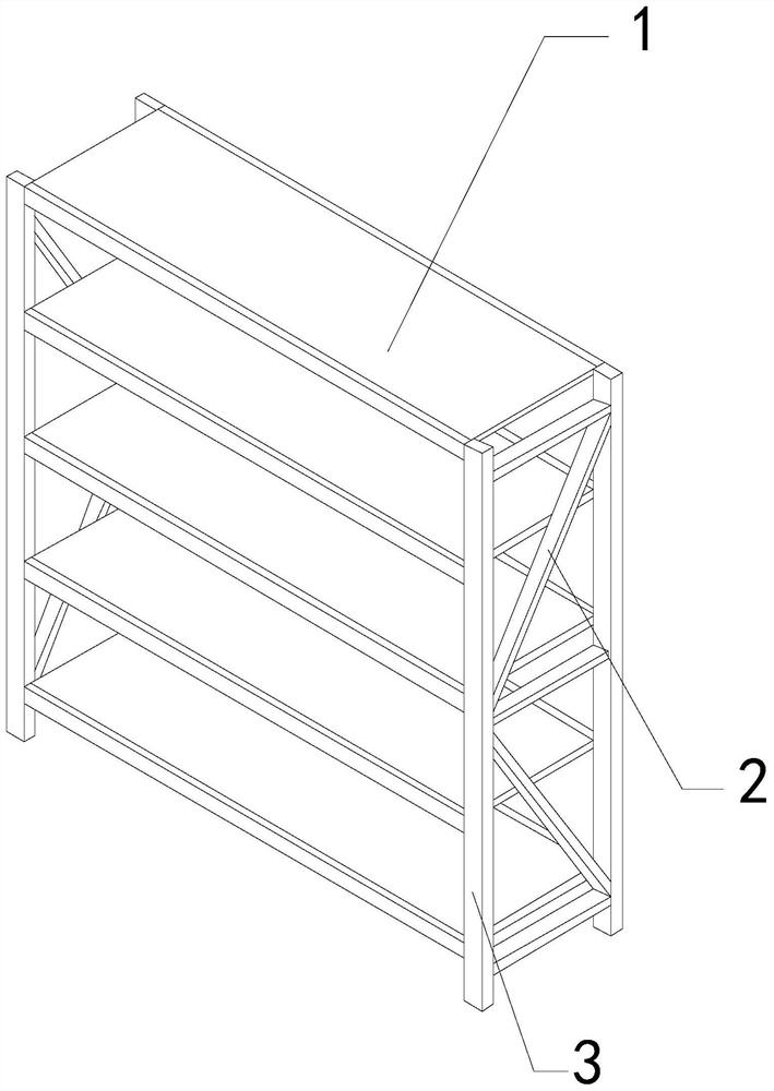
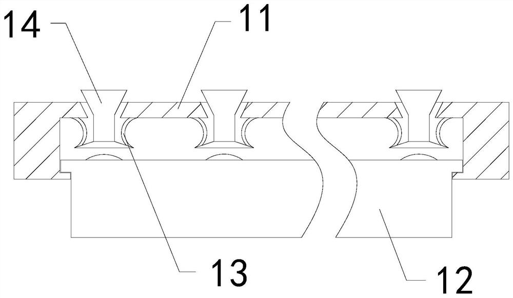
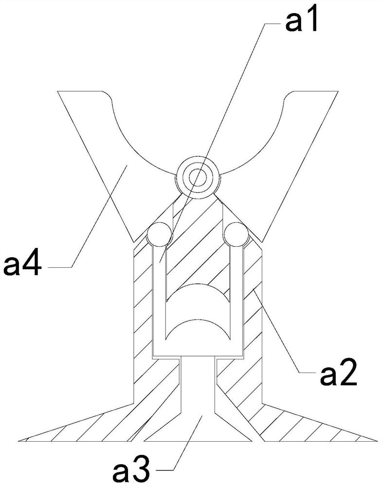
[0026] For example figure 1 -example Figure 5 Shown:

[0027] The present invention provides an intelligent logistics storage equipment, the structure of which includes a load plate 1, a fixed rod 2, and a support frame 3, the fixed rod 2 is welded to the inner side of the support frame 3, and the load plate 1 is embedded in the two support frames 3; the carrying plate 1 includes an upper connecting frame 11, a lower connecting plate 12, an elastic piece 13, and a telescopic block 14, and the inner side of the upper connecting frame 11 is movably engaged with the outer surface of the lower connecting plate 12, The elastic sheet 13 is installed between the inner side of the upper frame 11 and the telescopic block 14 , and the telescopic block 14 is slidably matched with the inside of the upper frame 11 .

[0028] Wherein, the telescopic block 14 includes a booster frame a1, a plate surface a2, a push-up block a3, and a clamping plate a4, the booster frame a1 is matched with ...

Embodiment 2

[0034] For example Figure 6 -example Figure 8 Shown:

[0035] Wherein, the air-permeable cavity a42 includes a circumscribed frame c1, an outer pushing frame c2, a linkage rod c3, and a position fixing rod c4. Engaged with the fixed rod c4, the fixed rod c4 is embedded in the inner position of the outer frame c1, through the swing force generated by the upward swing of the mechanism, the pusher frame c2 can be pushed along the outer frame with the cooperation of the linkage rod c3 c1 protrudes outward, so that the push frame c2 can push away the adhesive tape on the outside of the bounding frame c1.

[0036] Wherein, the pusher frame c2 includes an elastic strip c21, a transparent plate c22, a connecting rod c23, and a receiving frame c24. The right end of the connecting rod c23 is movable, and the connecting rod c23 is embedded in the inner position of the right end of the receiving frame c24. There are two transparent plates c22, and they are evenly distributed symmetri...


PUM


Abstract

The invention discloses intelligent logistics storage equipment which structurally comprises a bearing plate, a fixed rod and supporting frames, wherein the fixed rod is welded with the inner sides of the supporting frames; the bearing plate is embedded between the inner sides of the two supporting frames; spherical package placed on the bearing plate generates pressure on a telescopic block, so that the telescopic block downwards slides and extends out along an upper connecting frame, and thus, a bump on a lower jointing plate can generate upward thrust on an upper pushing block, upward pushing force can be generated on clamping plates by virtue of a pushing frame, the two clamping plates can clamp the spherical package to fix in position, and the spherical package is effectively prevented from a rolling condition on the bearing plate; an adsorbing plate is taken out upwards to swing under pull of the spherical package, so that an external pushing frame extends outwards along a fixing rod under matching with a linkage rod, and thus, the external pushing frame can push an adhesive tape to the outer side of the adsorbing plate.

Description

technical field [0001] The invention relates to the field of intelligent modern logistics, in particular to an intelligent logistics storage equipment. Background technique [0002] The intelligent logistics storage rack is mainly used for centralized storage of logistics parcels. By placing the logistics parcels directly on the loading plate of the intelligent logistics storage rack, the logistics parcels can be stored in a centralized manner. It is a common equipment in the logistics industry. Based on From the above description, the inventors found that the existing intelligent logistics storage equipment mainly has the following deficiencies, for example: [0003] Since the surface of the loading plate of the intelligent logistics storage rack is relatively flat, the heavy spherical package is easy to roll after being placed on the loading plate, and it is easy to push down other lighter packages in front during the rolling process, so that the logistics package The sto...

Claims


Application Information

Patent Timeline
Patent Type & Authority Applications(China)
IPC IPC(8): B65G47/91B65G1/04
CPCB65G47/91B65G1/04B65G2201/0285
Inventor 许华国
Owner 谢剑嘉
Learn More