
Shearing device for piston rubber ring machining

A technology of shearing device and rubber ring, which is applied in the direction of metal processing, etc., can solve the problems of inconvenient replacement of cutting mechanism, inability to tightly fix steel core and tube blank, and incomplete cutting of the shearing position.

Pending Publication Date: 2020-11-27
王水成
View PDF5 Cites 1 Cited by
  • Summary
  • Abstract
  • Description
  • Claims
  • Application Information

AI Technical Summary

Problems solved by technology

[0004] The purpose of the present invention is to provide a shearing device for processing piston rubber rings, to solve the problem that the existing shearing devices for processing piston rubber rings proposed in the above-mentioned background technology cannot correct the steel at the shearing position during use. The core and the upper and lower sides of the tube blank are tightly fixed. If the steel core and the tube blank are not tightly bonded, mutual sliding may occur and affect cutting, and there is no rotating structure, so the cutting effect cannot be deepened, and the shearing position is prone to incompleteness. The situation of cutting off, and it is not convenient to replace the cutting mechanism with different specifications and outer diameters

Method used


Image

  • Shearing device for piston rubber ring machining
  • Shearing device for piston rubber ring machining
  • Shearing device for piston rubber ring machining

Examples


Embodiment Construction

[0031] The following will clearly and completely describe the technical solutions in the embodiments of the present invention with reference to the accompanying drawings in the embodiments of the present invention. Obviously, the described embodiments are only some, not all, embodiments of the present invention. Based on the embodiments of the present invention, all other embodiments obtained by persons of ordinary skill in the art without making creative efforts belong to the protection scope of the present invention.

[0032]In the description of the present invention, unless otherwise stated, the meaning of "plurality" is two or more; the terms "upper", "lower", "left", "right", "inner", "outer" , "front end", "rear end", "head", "tail", etc. indicate the orientation or positional relationship based on the orientation or positional relationship shown in the drawings, and are only for the convenience of describing the present invention and simplifying the description, rather ...


PUM


Abstract

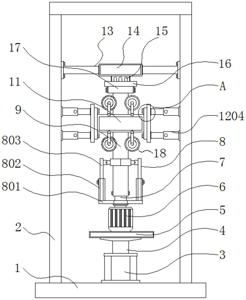
The invention discloses a shearing device for piston rubber ring machining, and relates to the technical field of piston rubber ring machining. The shearing device comprises a base, a clamping and fixing mechanism, a cutting mechanism and a movable positioning mechanism, a side plate is fixed to the outer side of the upper portion of the base, a hydraulic cylinder is installed above the middle ofthe base, and a piston rod is arranged above the hydraulic cylinder; and a supporting seat is fixed above the piston rod, a driving motor is installed above the supporting seat, a rotating shaft is arranged above the driving motor, an auxiliary steel core is arranged above the rotating shaft in a sleeving mode, and a rubber ring pipe blank is arranged on the outer side of the auxiliary steel core.The shearing device has the following beneficial effects that the auxiliary steel core and the rubber ring pipe blank on the outer side of the auxiliary steel core are conveniently driven to rotate through the arrangement of the driving motor and the rotating shaft, so that the cutting mechanism can rotate for a circle on the outer side of the auxiliary steel core and the rubber ring pipe blank to deepen the cutting effect; and through the arrangement of the hydraulic cylinder and the piston rod, the driving motor and the auxiliary steel core are conveniently driven to ascend and descend, andtherefore the shearing position is conveniently adjusted.

Description

technical field [0001] The invention relates to the technical field of processing piston rubber rings, in particular to a shearing device for processing piston rubber rings. Background technique [0002] The piston is the reciprocating part in the cylinder block of the automobile engine. The piston is the "heart" of the automobile engine. It bears alternating mechanical loads and thermal loads. It is one of the key components in the engine with the worst working conditions. The outer side of the piston is generally provided with a rubber ring, the general cross-section is circular, the rubber ring can be pressed out of the tube blank with dry glue, pierced through the steel core, and then cut after being vulcanized in a vulcanization tank. During the processing of the piston rubber ring, it needs to be cut, so a shearing device is required. [0003] The existing shearing device for piston rubber ring processing cannot tightly fix the steel core at the shearing position and ...

Claims


Application Information

Patent Timeline
Patent Type & Authority Applications(China)
IPC IPC(8): B26D5/08B26D7/06B26D7/01
CPCB26D5/08B26D7/01B26D7/06
Inventor 王水成
Owner 王水成
Learn More