Eureka AIR delivers breakthrough ideas for toughest innovation challenges, trusted by R&D personnel around the world.

Detection jig and detection method

A technology for detecting fixtures and fixture plates, which is applied in the direction of measuring devices, optical testing of flaws/defects, and material analysis through optical means. damage effect

Pending Publication Date: 2021-04-30
INTERFACE TECH CHENGDU CO LTD +2
View PDF12 Cites 0 Cited by
  • Summary
  • Abstract
  • Description
  • Claims
  • Application Information

AI Technical Summary

Problems solved by technology

However, when testing the appearance of the touch module, it is easy to produce new bad phenomena, resulting in poor testing results

Method used

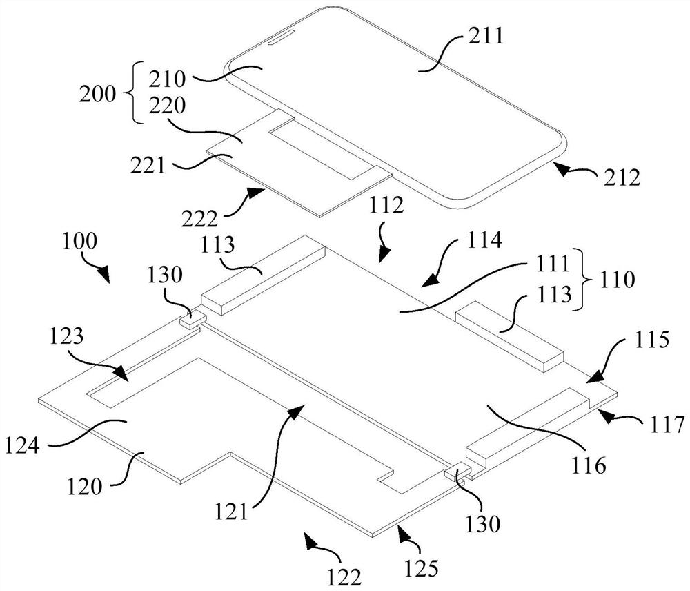
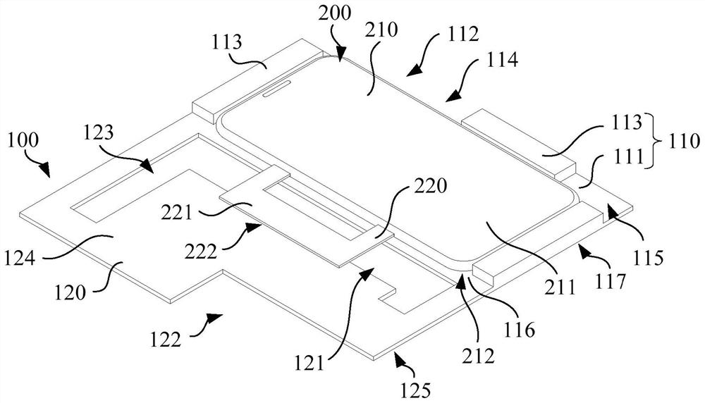
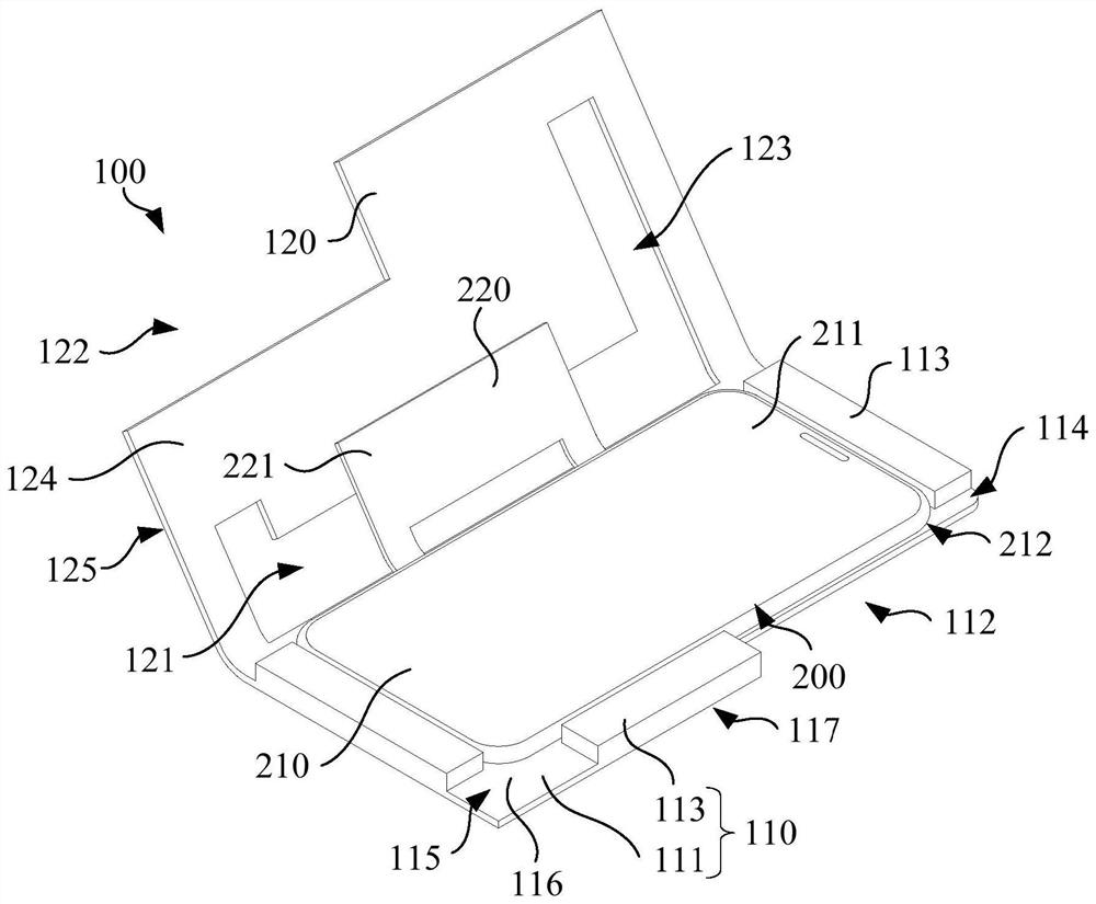

Image

  • Detection jig and detection method
  • Detection jig and detection method
  • Detection jig and detection method

Examples


Embodiment Construction

[0032] In order to make the above objects, features and advantages of the present invention more comprehensible, specific implementations of the present invention will be described in detail below in conjunction with the accompanying drawings. In the following description, numerous specific details are set forth in order to provide a thorough understanding of the present invention. However, the present invention can be implemented in many other ways different from those described here, and those skilled in the art can make similar improvements without departing from the connotation of the present invention, so the present invention is not limited by the specific embodiments disclosed below.

[0033] In describing the present invention, it should be understood that the terms "center", "longitudinal", "transverse", "length", "width", "thickness", "upper", "lower", "front", " Back", "Left", "Right", "Vertical", "Horizontal", "Top", "Bottom", "Inner", "Outer", "Clockwise", "Counte...


PUM


Abstract

The invention relates to a detection jig and a detection method. The detection jig comprises a first jig plate used for limiting a workpiece, wherein the first jig plate comprises a first inner side face and a second inner side face which are arranged oppositely; and a second jig plate which is connected with the first jig plate, wherein the second jig plate comprises a second inner side face and a second outer side face which are arranged back to back, the detection jig has an open state and a closed state, and when the detection jig is in the open state, the first inner side face and the second inner side face are located on the same side of the workpiece, when the detection jig is in the closed state, the first inner side surface is opposite to the second inner side surface; an avoiding groove is formed in the second jig plate and used for being opposite to a flexible element of the workpiece. When the detection jig is used for detecting the workpiece, the hands of the human body can complete detection of all surfaces of the workpiece without contacting with the workpiece, and the detection effect is good.

Description

technical field [0001] The invention relates to the field of touch module detection, in particular to a detection fixture and a detection method. Background technique [0002] With the development of touch technology, more and more electronic devices are equipped with touch modules to realize touch sensing functions. The touch module includes interconnected glass cover plates and flexible printed circuit boards (Flexible Printed Circuit, FPC). During the manufacturing process, it is usually necessary to inspect the appearance of the two opposite surfaces of the touch panel to prevent the appearance from affecting the electronic equipment. usage of. However, when inspecting the appearance of the touch module, new defects are likely to occur, resulting in poor inspection results. Contents of the invention [0003] Based on this, it is necessary to provide a detection fixture and a detection method to improve the detection effect. [0004] A detection fixture, comprising: ...

Claims


Application Information

Patent Timeline
IPC IPC(8): G01N21/01G01N21/88G01N21/956G01N21/84
CPCG01N21/01G01N21/8803G01N21/8851G01N21/956G01N21/84G01N2021/0112G01N2021/95638G01N2021/8411
Inventor 解占松王国峰易星毛华军
Owner INTERFACE TECH CHENGDU CO LTD
Why Eureka
Eureka Blog
Learn More