
Indoor ceiling antenna for communication system

An indoor ceiling antenna and communication system technology, which is applied in the direction of antenna, antenna support/installation device, radiation element structure, etc., can solve the problems of Internet stuttering, random distribution density of personnel flow, etc., and achieve the effect of ensuring smooth network

Pending Publication Date: 2021-04-30
王世杰
View PDF0 Cites 0 Cited by
  • Summary
  • Abstract
  • Description
  • Claims
  • Application Information

AI Technical Summary

Problems solved by technology

[0004] The invention provides an indoor ceiling antenna for a communication system, which has the advantages of mutual connection and cooperation of the indoor ceiling antennas, which can simultaneously disperse the network in a densely populated place to ensure that users can surf the Internet smoothly, and solve the distribution density of personnel flow in the shopping mall Casual, it will cause the problem of Internet lag in a certain place

Method used


Image

  • Indoor ceiling antenna for communication system
  • Indoor ceiling antenna for communication system
  • Indoor ceiling antenna for communication system

Examples


Embodiment Construction

[0019] The following will clearly and completely describe the technical solutions in the embodiments of the present invention with reference to the accompanying drawings in the embodiments of the present invention. Obviously, the described embodiments are only some, not all, embodiments of the present invention. Based on the embodiments of the present invention, all other embodiments obtained by persons of ordinary skill in the art without making creative efforts belong to the protection scope of the present invention.

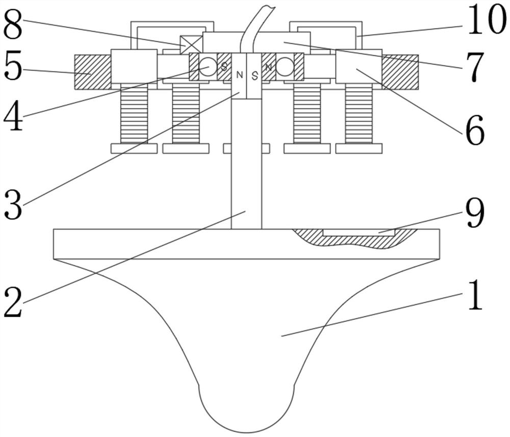
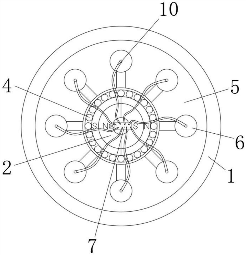
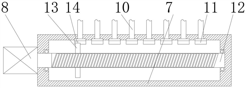
[0020] see Figure 1-7 , an indoor ceiling antenna for a communication system, comprising an antenna 1, the middle part of the upper surface of the antenna 1 is fixedly fitted with an installation shaft 2, the outer surface of the upper part of the installation shaft 2 is set as a permanent magnet 3, and the outer surface of the permanent magnet 3 is magnetically attracted The rolling bearing 4 is set in the suit, and the outer surface of the rolling bearing 4...


PUM


Abstract

The invention relates to the technical field of communication equipment, and discloses an indoor ceiling antenna for a communication system; the antenna comprises an antenna body, a mounting shaft fixedly sleeves the middle part of the upper surface of the antenna body, a permanent magnet is arranged on the outer surface of the upper part of the mounting shaft, and a rolling bearing magnetically sleeves the outer surface of the permanent magnet. And the outer surface of the rolling bearing is fixedly sleeved with a mounting plate. According to the indoor ceiling antenna for the communication system, through the number configuration of the electromagnetic coils, after the antennas are installed and distributed, eight antennas are distributed around the antenna in the middle, and under the cooperation of the electromagnetic coils, the antenna in the middle can rotate to be matched with other antennas, so that any antenna can be rotatably matched with the antennas around; therefore, after the network card is changed due to the fact that the load of a certain antenna network is increased, the surrounding antennas can rotate to align the side with high radiation intensity to the antenna with high load, network resources are distributed, and network smoothness of indoor personnel is guaranteed.

Description

technical field [0001] The invention relates to the technical field of communication equipment, in particular to an indoor ceiling-mounted antenna for a communication system. Background technique [0002] With the rapid increase of users in cities and more and more high-rise buildings, the traffic density and coverage requirements are also rising. Due to the shielding and absorption functions of the building itself, the radio waves have a large loss, resulting in weak mobile signals. Field strength areas or blind areas, and buildings similar to large shopping malls and conference centers, because the use density of mobile phones is relatively high, the local network capacity cannot meet the needs of users, and wireless channels will be congested. Indoor ceiling antennas can be very good To solve the above problems, the indoor ceiling antenna is a kind of mobile communication antenna, which is mainly used for indoor signal coverage. The indoor ceiling antenna belongs to the b...

Claims


Application Information

Patent Timeline
IPC IPC(8): H01Q3/02H01Q1/12H01Q1/36
CPCH01Q1/12H01Q1/36H01Q3/02
Inventor 不公告发明人
Owner 王世杰
Learn More