Light transmittance adjustment device

A technology for adjusting device and light transmittance

Active Publication Date: 2022-06-03
SHANGHAI MICRO ELECTRONICS EQUIP (GRP) CO LTD
View PDF6 Cites 0 Cited by
  • Summary
  • Abstract
  • Description
  • Claims
  • Application Information

AI Technical Summary

Problems solved by technology

[0004] The object of the present invention is to provide a light transmittance adjustment device to solve the problem of changing the polarization state of incident light by utilizing the existing light transmittance adjustment device

Method used


Image

  • Light transmittance adjustment device
  • Light transmittance adjustment device
  • Light transmittance adjustment device

Examples


Embodiment 1

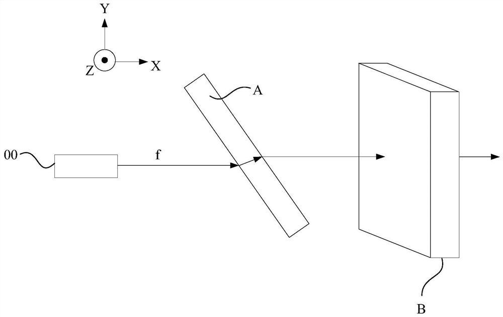
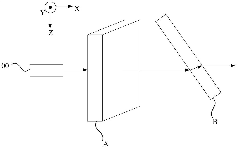
[0045] figure 2 It is a schematic structural diagram of a light transmittance adjustment device provided in Embodiment 1 of the present invention, image 3 Provided for the embodiment of the present invention figure 2 A top view of the device, such as figure 2 and image 3 As shown, the device may include a light source 00 and at least two rotatable light-transmitting plates arranged along the X direction, wherein, figure 2 and image 3 Two rotatable light-transmitting plates including the rotatable light-transmitting plate A and the rotatable light-transmitting plate B are taken as an example for illustration.

[0046] Specifically, the light source 00 is used to provide the incident light f, the light source 00 can be a laser emitter, and the polarization degree of the incident light f can be 0, and the incident light also has a first A beam and a second beam. At the same time, refer to figure 2 and image 3 , the incident direction of the incident light is defi...

Embodiment 2

[0079] Referring to the first embodiment, when the incident light passes through the light-transmitting plate, it will be refracted, resulting in a certain deviation of its optical path. For example, refer to figure 2 As shown, after the incident light f passes through the rotatable light-transmitting plate A, its optical path has a certain offset in the XY plane, refer to image 3 As shown, after the incident light passes through the rotatable light-transmitting plate B, its optical path has a certain deviation in the XZ plane.

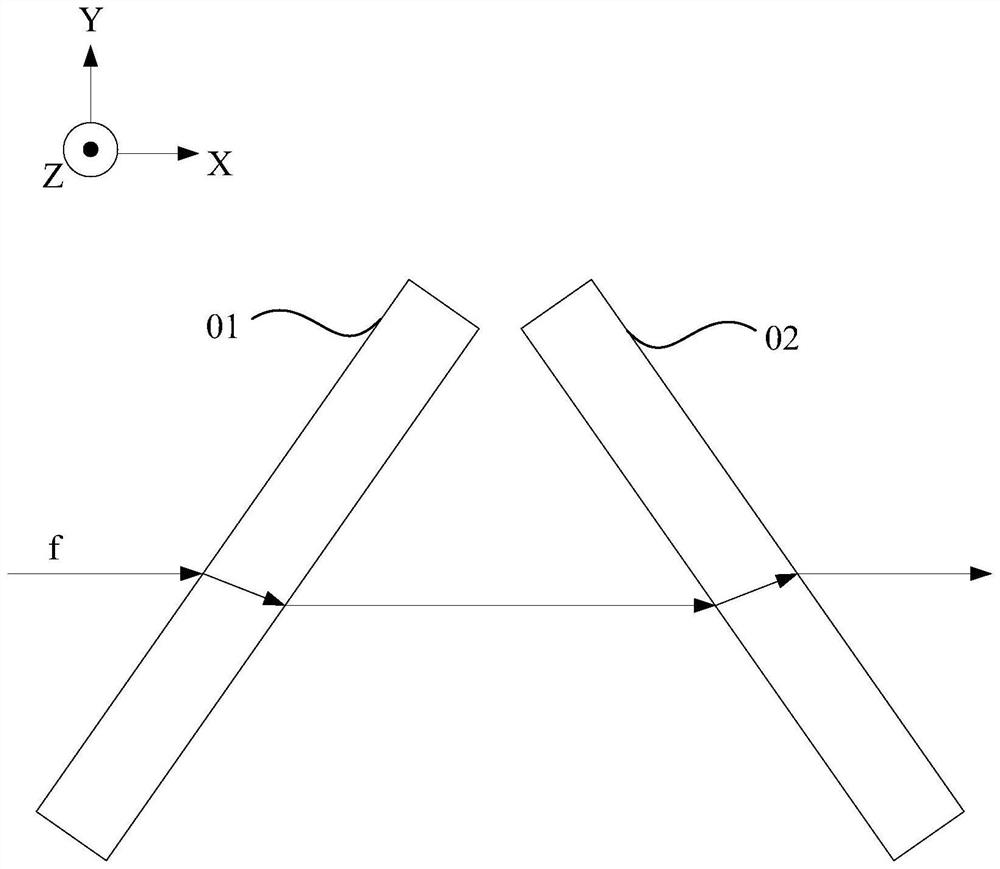
[0080] Based on this, in order to prevent the optical path of the incident light from shifting, on the basis of the first embodiment, the N should be an even number, that is, the number of light-transmitting plates included is a multiple of four. In addition, the rotation directions of any N / 2 rotatable light-transmitting plates among the any N rotatable light-transmitting plates are the same, and the rotation directions of the remaining N / 2 rotatab...

Embodiment 3

[0100] Since the rotation angles of the 2N rotatable light-transmitting plates are between 0° and 90°, when the rotation angles are limited, it is impossible to adjust the light transmittance adjustment in a wider range. Based on this, At least one fixed light-transmitting plate arranged perpendicular to the direction of incident light can be added to expand the adjustment range of light transmittance. Figure 10 A schematic structural diagram of a light transmittance adjustment device provided in Embodiment 3 of the present invention, as shown in Figure 10 As shown, remove the 2N rotatable transparent plates (for example Figure 10 In addition to the first rotatable light-transmitting plate 11, the second rotatable light-transmitting plate 12, the third rotatable light-transmitting plate 21 and the fourth rotatable light-transmitting plate 22), the at least two light-transmitting plates also have A fixed transparent plate C arranged perpendicular to the direction of inciden...


PUM

PropertyMeasurementUnit
angle of incidenceaaaaaaaaaa

Abstract

The invention provides a light transmittance adjustment device, comprising: a light source, used to provide incident light, the incident direction of the incident light is the X direction, and the direction perpendicular to the X direction is the Y direction, defined by the X direction and the Y direction XY plane, the direction perpendicular to the XY plane is the Z direction; at least two light-transmitting plates arranged along the X-direction, at least two light-transmitting plates have 2N rotatable light-transmitting plates, N is a positive integer, and 2N rotatable Any N rotatable light-transmitting panels in the light-transmitting panels rotate around the Y direction, and the other N rotatable light-transmitting panels rotate around the Z direction, and by rotating 2N rotatable light-transmitting panels, any N rotatable The one-to-one difference between the transmissivity of the light-transmitting plate and the other N rotatable light-transmitting plates for incident light is less than or equal to a predetermined value. The light transmittance adjusting device provided by the present invention can ensure that the polarization degree of the outgoing light is consistent with that of the incident light without changing the polarization state of the light beam, thereby ensuring accurate execution of subsequent operations.

Description

technical field [0001] The invention relates to the field of optics, in particular to a device for adjusting light transmittance. Background technique [0002] In the field of optics, light beams of different intensities are usually used to perform corresponding operations (such as exposure operations) to meet process requirements. In the related art, the incident light will be emitted through the light-transmitting plate, and the incident angle of the incident light is adjusted by adjusting the rotation angle of the light-transmitting plate to adjust the transmittance of the incident light, so as to realize the transmission of the incident light Adjustment of the rate to obtain different intensities of outgoing light. [0003] However, since the reflectivity of the light-transmitting plate to the light beam whose polarization direction is parallel to the incident surface (that is, the plane formed by the incident light and the reflected light) is different from the reflect...

Claims


Application Information

Patent Timeline
Patent Type & Authority Patents(China)
IPC IPC(8): G02B26/02
CPCG02B26/02
Inventor 王彩红侯宝路
Owner SHANGHAI MICRO ELECTRONICS EQUIP (GRP) CO LTD
Why Eureka
Try Eureka