Exposure machine and shading blade

A technology of shading blades and exposure machines, which is applied in the direction of photomechanical equipment, microlithography exposure equipment, and photolithography exposure equipment, etc., and can solve the problem of damage to the photomask protective film 400, affecting the quality of the exposure process, and high risk of scratches, etc. problem, to achieve the effect of reducing air pressure drop, ensuring exposure quality, and preventing abnormal graphics

Active Publication Date: 2018-10-26
TCL CHINA STAR OPTOELECTRONICS TECH CO LTD
View PDF6 Cites 0 Cited by
  • Summary
  • Abstract
  • Description
  • Claims
  • Application Information

AI Technical Summary

Problems solved by technology

Since the bottom of the photomask protection film 400 is extremely small (usually 3mm) from the top of the first front shading blade 101 and the first rear shading blade 102, it is possible to It will cause the air pressure between the photomask protection film 400 and the first front shading blade 101 and the first rear shading blade 102 to decrease, thereby causing the photomask protection film 400 to bend downwards and rub against the first front shading blade 101 and the first rear shading blade 102. The top of the first rear light-shielding blade 102 causes damage to the mask protection film 400 and affects the quality of the exposure process
Especially when the exposure machine performs mask OPAF sensor calibration (mask OPAF sensor calibration), the first front shading blade 101 needs to move quickly to one side of the first rear shading blade 102, and this large-scale rapid movement The resulting drop in air pressure is large, and the downward bending of the photomask protective film 400 is also more serious, and the risk of scratches is also greater

Method used


Image

  • Exposure machine and shading blade
  • Exposure machine and shading blade
  • Exposure machine and shading blade

Examples


Embodiment Construction

[0025] In order to further illustrate the technical means adopted by the present invention and its effects, the following describes in detail in conjunction with preferred embodiments of the present invention and accompanying drawings.

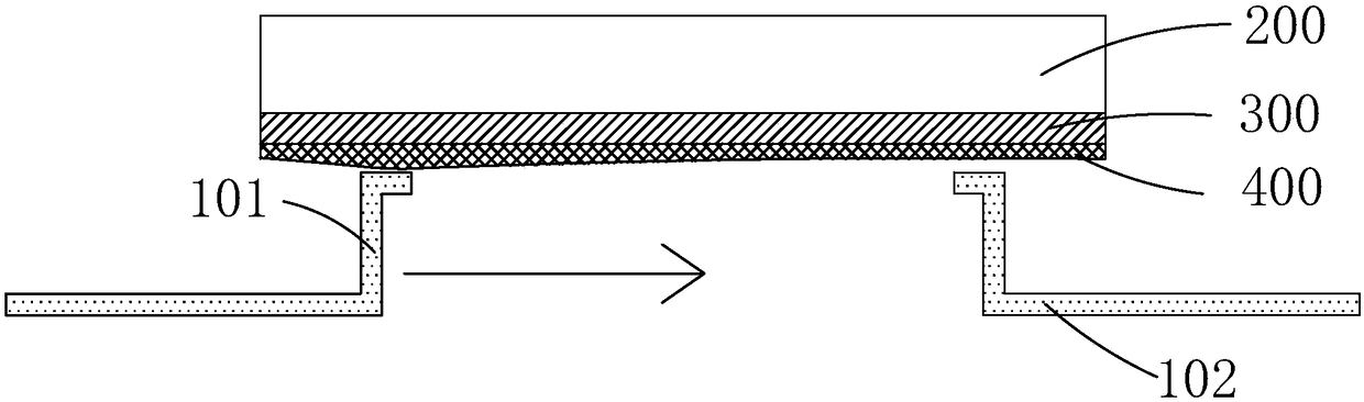
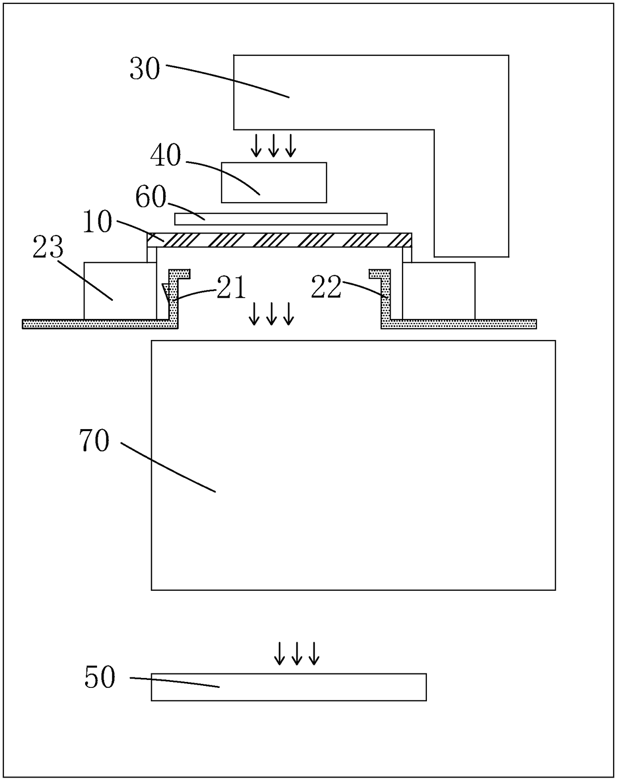
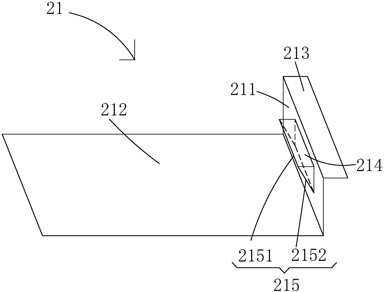
[0026] see Figure 2 to Figure 4 , the present invention provides an exposure machine, comprising: a photomask stage 10, a photomask 61, a photomask protection film 62, a first front shading blade 21 and a first rear shading blade 22;

[0027] The photomask 61 is arranged under the photomask stage 10, the photomask protection film 62 blocks the side surface of the photomask 61 away from the photomask stage 10, and the first front shading blade 21 and the first rear shading blade 22 are located on the side of the photomask protection film 62 away from the photomask 61 and spaced from the photomask protection film 62, and the first front shading blade 21 and the first rear shading blade The blades 22 are relatively arranged along the horizontal...


PUM

PropertyMeasurementUnit
thicknessaaaaaaaaaa

Abstract

The invention provides an exposure machine and a masking blade. The exposure machine has the advantages that a vertical part of a first front masking blade is provided with an opening, the air can flow through the opening when the first front masking blade is moved, and the decreasing of air pressure between the first front masking blade and a light cover protecting film is reduced when the first front masking blade is moved, so that the scratching of the light cover protecting blade is avoided; masking plates are arranged at the top part and side part of the opening, so that the leakage of the ultraviolet light for exposure via the opening is avoided, the masking effect of the first front masking blade and the exposure effect of the exposure machine are guaranteed, and the abnormality of patterns is prevented.

Description

technical field [0001] The invention relates to the technical field of display manufacturing, in particular to an exposure machine and a shading blade. Background technique [0002] In the field of display technology, flat-panel displays such as Liquid Crystal Display (LCD) and Organic Light Emitting Diode (OLED) have gradually replaced CRT displays, and are widely used in LCD TVs, mobile phones, personal digital assistants, digital Cameras, computer or laptop screens, etc. [0003] In the manufacturing process of flat panel displays such as the Array process of liquid crystal displays, an exposure machine is often used to perform an exposure process to pattern the corresponding film layer. Existing exposure machines generally include: a photomask stage, a light source corresponding to the photomask stage, an amplifying optical path arranged under the photomask stage, a substrate stage arranged under the amplifying optical path, and a light source arranged under the photoma...

Claims


Application Information

Patent Timeline
Patent Type & Authority Patents(China)
IPC IPC(8): G03F7/20
CPCG03F7/7015
Inventor 王维林明文江敏成许俊安熊定蔡在秉
Owner TCL CHINA STAR OPTOELECTRONICS TECH CO LTD
Why Eureka
Try Eureka