A medical gastric lavage device

A gastric lavage and internal medicine technology, which is applied in the direction of enema/irrigator, other medical devices, and drug devices. Stomach efficient effect

Active Publication Date: 2022-07-12
THE AFFILIATED HOSPITAL OF QINGDAO UNIV
View PDF12 Cites 0 Cited by
  • Summary
  • Abstract
  • Description
  • Claims
  • Application Information

AI Technical Summary

Problems solved by technology

[0003] The existing gastric lavage device for internal medicine has a simple structure. Generally, two sets of syringes and two gastric tubes are used to perform injection and extraction operations. The two sets of operations are likely to cause discomfort to the patient and cause damage to the gastric mucosa. The operation is difficult and cannot be performed manually. Accurate control of the flow rate can easily cause abnormal gastric pressure in patients

Method used


Image

  • A medical gastric lavage device
  • A medical gastric lavage device
  • A medical gastric lavage device

Examples


Embodiment 1

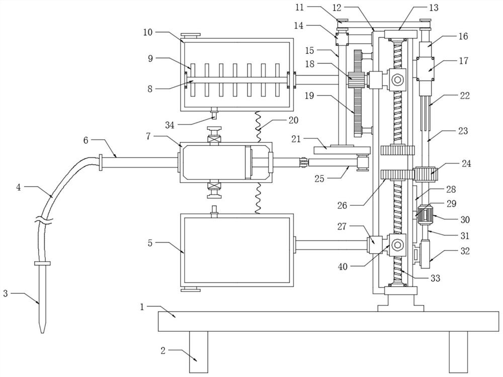
[0023] see Figure 1-3 , a medical gastric lavage device, comprising a support base 1 and a gastric lavage liquid tank 10, a bracket 13 is arranged on the upper surface of the support base 1, a screw 33 is symmetrically arranged between the brackets 13, and the screw 33 is rotatably connected to both ends of the bracket 13 The surface of the screw 33 on the upper and lower sides is provided with a nut 40, the nut 40 can move up and down in the vertical direction with the rotation of the screw 33, and the auxiliary gear 26 is fixedly installed at the ends of the screw 33 on the upper and lower sides that are close to each other. A drive motor 30 is provided on the right side wall surface of the bracket 13, and the output end of the drive motor 30 is extended and fixedly connected to the main gear 24. In order to drive the upper and lower screws 33 to rotate, the bottom connection of the drive motor 30 can push the drive motor 30 to move up and down When driving the upper or low...

Embodiment 2

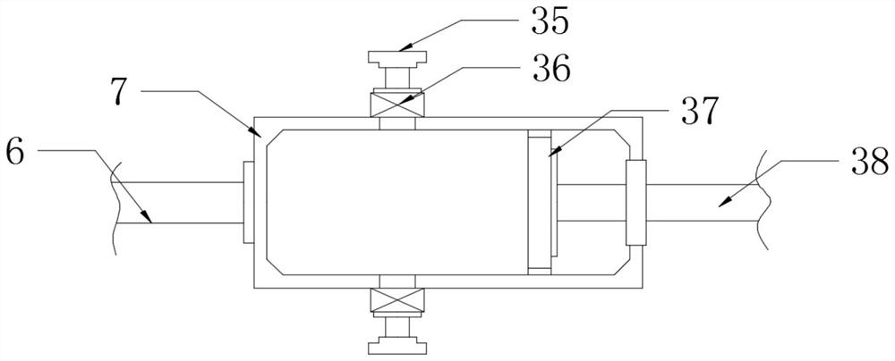
[0031] see Figure 1-4, On the basis of Embodiment 1, in order to push the piston 37 to reciprocate horizontally in the piston cylinder 7, the pushing mechanism includes a runner 21, and the lower surface edge of the runner 21 is movably connected to the push rod 1 25, the The end of the push rod 1 25 away from the runner 21 is movably connected to the push rod 2 38, and the end of the push rod 2 38 away from the push rod 1 25 is fixedly connected with the piston 37. In order to drive the runner 21 to rotate, the upper part of the main gear 24 is fixed The positioning rod 23 is connected, a positioning sleeve 16 is arranged above the positioning rod 23, the positioning rod 23 can slide up and down in the positioning sleeve 16, and a plurality of slots 41 are arranged in the positioning sleeve 16, and the positioning rod The surface of 23 is provided with a plurality of card seats 22 which are installed in cooperation with the card grooves 41 to ensure that the positioning rod ...


PUM


Abstract

The invention discloses a medical gastric lavage device, which relates to the technical field of medical equipment. It includes a support base and a gastric lavage liquid tank. A bracket is arranged on the upper surface of the support base, and a screw is symmetrically arranged between the brackets. Both ends of the screw and the bracket are rotatably connected. The nut and the ends of the screw that are close to each other are fixedly installed with auxiliary gears, and the surface of the right side wall of the bracket is provided with a driving motor. The nut above drives the gastric lavage liquid tank to move down through the connecting rod, and the infusion tube is inserted into the drainage port through the elastic sealing ring. , the push mechanism pushes the piston to reciprocate horizontally in the piston cylinder, and transport the cleaning solution in the gastric lavage tank to the human body. After cleaning, the lower screw rotates, the nut drives the liquid storage tank to move up through the connecting rod, and the top wall of the liquid storage tank moves upward. The infusion tube is inserted into the drainage port at the bottom of the piston cylinder, and the piston moves horizontally in the piston cylinder to pump the gastric juice from the human body into the liquid storage tank. .

Description

technical field [0001] The invention relates to the technical field of medical equipment, in particular to a gastric lavage device for internal medicine. Background technique [0002] Gastric lavage is to pour a specific liquid into the stomach cavity, mix it with the reactants in the stomach cavity to dilute and discharge, and then repeat the above operation to achieve the purpose of taking out the poison in the stomach cavity. Its purpose is to remove the unabsorbed poison in the stomach or clean the stomach cavity, and it is clinically used to prepare for gastric surgery and examination. [0003] The existing gastric lavage device for internal medicine has a simple structure, and generally two sets of syringes and two gastric tubes are used to perform injection and extraction operations. The two sets of operations can easily cause discomfort to the patient and cause damage to the gastric mucosa, which is difficult to operate and cannot be operated manually. Accurate cont...

Claims


Application Information

Patent Timeline
Patent Type & Authority Patents(China)
IPC IPC(8): A61M3/02
CPCA61M3/0254A61M2210/1053
Inventor 董泽华刘莹周维桂
Owner THE AFFILIATED HOSPITAL OF QINGDAO UNIV
Why Eureka
Try Eureka