Table type outdoor heating furnace

A technology for heating stoves and outdoors, applied in the field of heating stoves, can solve problems such as inconvenience, dumping, and leakage, and achieve the effect of improving stability

Inactive Publication Date: 2021-05-07
福建易辰达机械有限公司
View PDF4 Cites 0 Cited by
  • Summary
  • Abstract
  • Description
  • Claims
  • Application Information

AI Technical Summary

Problems solved by technology

[0004] However, the applicant found during actual use that when the liquid-carrying article is placed on the support platform, it leaks or falls over, so that the liquid stays from the support platform to the edge of the support platform and remains, dripping to the bottom of the support platform. on the user's body, causing an inconvenience and therefore requiring improvement

Method used


Image

  • Table type outdoor heating furnace
  • Table type outdoor heating furnace
  • Table type outdoor heating furnace

Examples


Embodiment 1

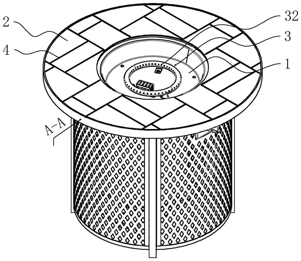
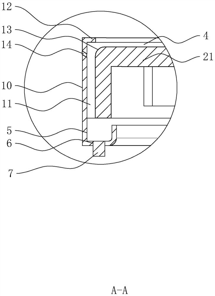
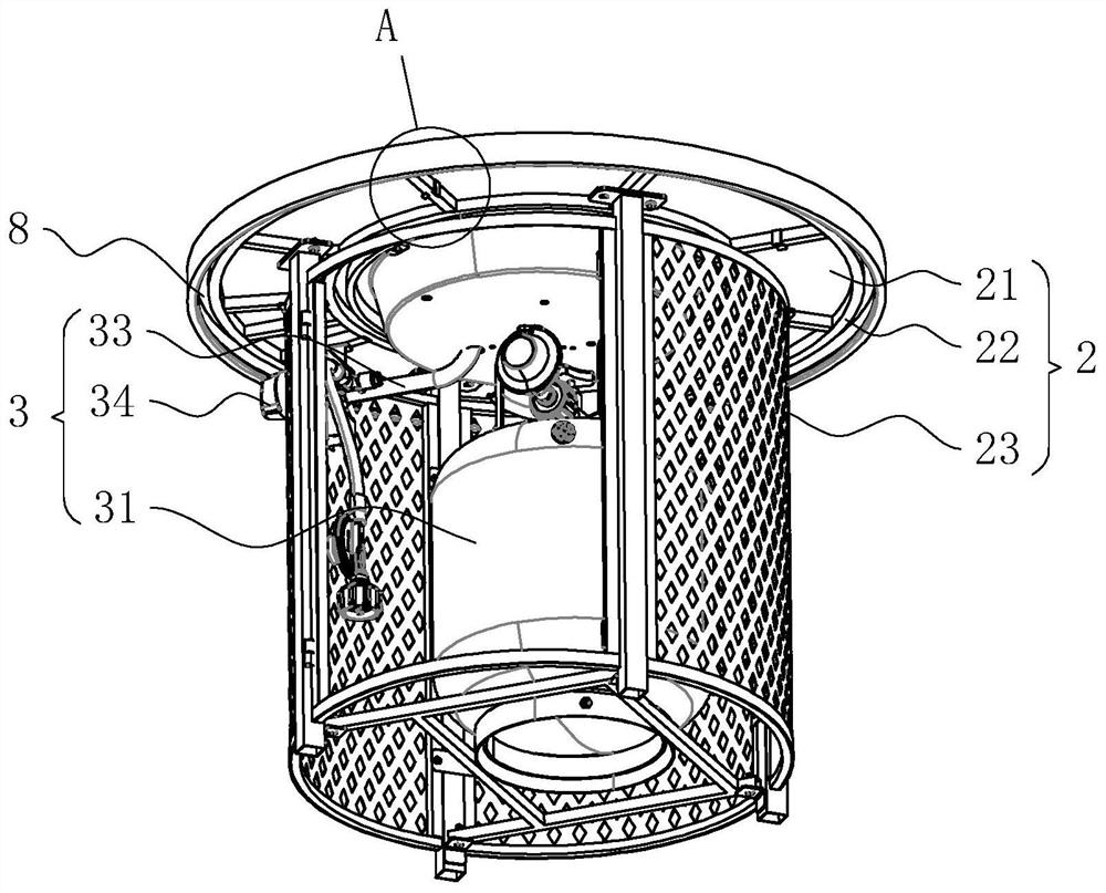
[0041] refer to figure 1 , figure 2 As shown, the heating furnace includes a brazier 1, a support platform 2, and a fire supply device 3. The brazier 1 is fixed to the middle of the support platform 2, the fire supply device 3 is arranged on the lower side of the brazier 1, and a number of diversion grooves are opened on the upper end of the support platform 2. 4. Each diversion groove 4 is connected to the outer edge of the support platform 2, and the outer edge ring of the support platform 2 is provided with a liquid collection groove 5 communicating with each diversion groove 4, and the liquid collection groove 5 is located under the diversion groove 4 In this way, the liquid on the support platform 2 can be guided and collected, reducing the phenomenon that the liquid on the support platform 2 flows onto the user. Specifically, a discharge port 6 is provided at the bottom of the liquid collection tank 5, and a rubber plunger 7 is sealed and blocked on the discharge port ...

Embodiment 2

[0048] refer to Figure 5 , Figure 6 As shown, the difference between this embodiment and Embodiment 1 is that each diversion groove 4 is arranged in a ring shape and is enlarged sequentially from the inner side to the outer side of the support platform 2, and the support platform 2 is also provided with channels that communicate with each diversion groove. From the groove 4 to the second guide groove 15 on the outer edge of the support platform 2 , each second guide groove 15 is communicated with the liquid collection tank 5 .

[0049] Further, refer to Figure 5 , Figure 6 As shown, the support platform 2 is formed with a number of ring-shaped retaining bars 16, each retaining bar 16 is arranged in a triangular cross-section, and each retaining bar 16 is arranged on the side of the diversion groove 4 close to the outer edge of the support platform 2 , The bar 16 plays the role of blocking and slowing down the flow.

[0050] The implementation principle of Embodiment 2 ...


PUM


Abstract

The invention relates to a table type outdoor heating furnace, and relates to the technical field of heating furnaces. The table type outdoor heating furnace mainly comprises a brazier, a supporting table and a fire supply device, the brazier is fixed to the middle of the supporting table, the fire supply device is arranged at the lower side of the brazier, a plurality of flow guide grooves are formed in the upper end face of the supporting table, and the flow guide grooves communicate with the outer edge of the supporting table; and liquid collecting grooves communicated with the flow guide grooves are formed at the outer edge of the supporting table in the circumferential direction, and the liquid collecting grooves are located at the lower sides of the flow guide grooves, so that liquid on the supporting table can be guided and collected, and the phenomenon that the liquid on the supporting table flows to the body of a user is reduced. The table type outdoor heating furnace has the effect of reducing liquid flowing to the body of the user from the supporting table.

Description

technical field [0001] The present application relates to the technical field of heating stoves, in particular to a table-type outdoor heating stove. Background technique [0002] At present, heating stove is a kind of heating equipment that is more common in cold regions, and existing stove is generally heated by coal, gas or natural gas as energy. When people are heating and eating around the stove, due to the single function of the existing heating stove, most of them only have the heating function, which makes it inconvenient to place and take some items (such as beverages, food, etc.) around, resulting in the loss of the stove. Applicability is poor. [0003] Therefore, the applicant discloses a table-shaped heating stove in the Chinese patent whose publication number is CN111795422A, which includes a support platform, a brazier and a fire supply device. Inside the platform, it is used to provide a fire source for the brazier for heating, and the opening of the brazie...

Claims


Application Information

Patent Timeline
IPC IPC(8): F24D15/02F24D19/00
CPCF24D15/02F24D19/00
Inventor 吴培兵
Owner 福建易辰达机械有限公司
Why Eureka
Try Eureka