A kind of hand-held green printing equipment and printing method
A kind of printing equipment and hand-held technology, which is applied in hand-held green printing equipment and printing fields, can solve the problems of affecting the printing effect, ink pushing, printing ghosting, etc., achieve smooth sliding, reduce ink waste, and reduce gaps Effect
- Summary
- Abstract
- Description
- Claims
- Application Information
AI Technical Summary
Problems solved by technology
Method used
Image
Examples
Embodiment 1
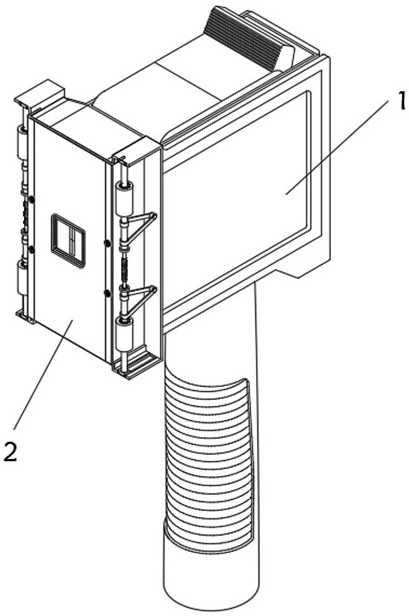
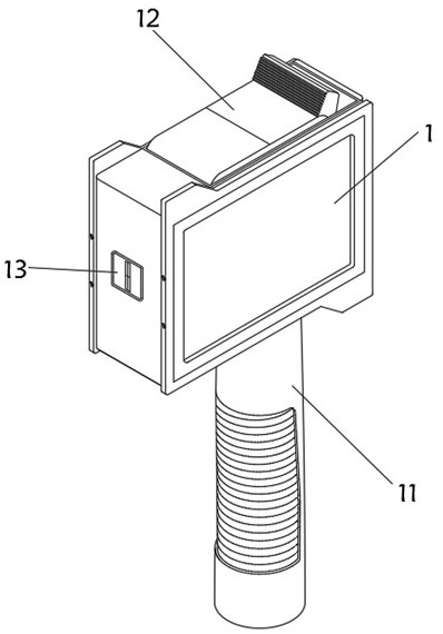
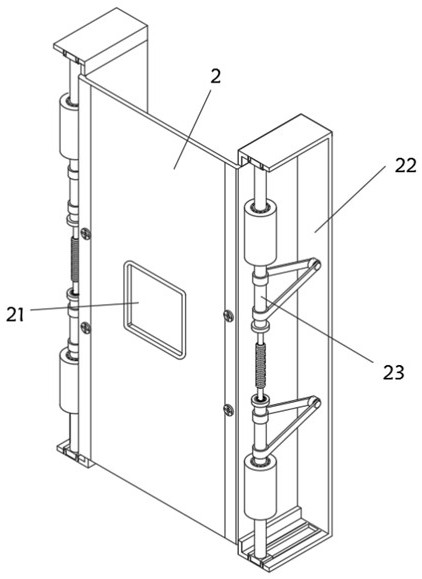
[0040] The invention provides a handheld green printing equipment and printing method, such as Figure 1-Figure 8 As shown, it includes a print head 1, a hand grip 11 for holding is installed on the bottom of the print head 1, an ink cartridge 12 for ink supply is installed on the inner wall of the print head 1, and one side of the print head 1 is provided with an ink outlet for ink discharge. Printing hole 13, the side of the printing head 1 close to the printing hole 13 is provided with a baffle 2, and the center of the baffle 2 is provided with a through hole 21 that is adapted to the size of the printing hole 13. After the baffle 2 is installed, the through hole 21 and the The printing holes 13 are located at the same position, which is convenient for the ink to be ejected from the printing holes 13, and the packaging box is printed. Side frames 22 are symmetrically installed on both sides of the baffle plate 2, and a pair of positioning devices 23 are symmetrically install...
Embodiment 2
[0047] As the second embodiment of the present invention, in order to enhance the toughness between the two positioning devices 23, the present invention is also provided with a connecting rod 3, such as Figure 9 As shown, a connecting rod 3 is installed between the two limiting plates 236, and the connecting rod 3 is made of tough plastic material.
[0048] In the present embodiment, the raw materials of the connecting rod 3 include PVC resin, methyl tin heat stabilizer, stearic acid, MBS resin and rubber particles, and the preparation method thereof is as follows:
[0049] (1) Add PVC resin, methyl tin heat stabilizer, stearic acid, MBS resin and rubber particles into a high-speed mixer and mix for 5 minutes;
[0050] (2) Mix the good
Embodiment 3
[0052] As the third embodiment of the present invention, in order to prevent the sliding block 231 from slipping off in the chute 222, the present invention further improves the sliding block 231. As a preferred embodiment, as Figure 10-Figure 12 As shown, the two ends of the slider 231 are symmetrically installed with an "L"-shaped plate 2311, and the "L"-shaped plate 2311 and the slider 231 are integrally formed, so that the "L"-shaped plate 2311 and the slider 231 have strong integrity and are not easy to There is a gap groove 2312 between the "L"-shaped plate 2311 and the slider 231. Limiting grooves 223 are symmetrically provided at both ends of the connecting plate 221 close to the sliding groove 222. The "L"-shaped plate 2311 and the limiting groove 223 are slidably connected. , through the "L"-shaped plate 2311 sliding in the limiting groove 223, the sliding block 231 can be ensured to slide smoothly in the sliding groove 222, and the sliding block 231 can be positione...
PUM
 Abstract
Description
Claims
Application Information
 - R&D
- Intellectual Property
- Life Sciences
- Materials
- Tech Scout
- Unparalleled Data Quality
- Higher Quality Content
- 60% Fewer Hallucinations
Browse by: Latest US Patents, China's latest patents, Technical Efficacy Thesaurus, Application Domain, Technology Topic, Popular Technical Reports.
© 2025 PatSnap. All rights reserved.Legal|Privacy policy|Modern Slavery Act Transparency Statement|Sitemap|About US| Contact US: help@patsnap.com


