Machine head and cooling fan

A machine head and air duct technology, applied in the field of cooling fans, can solve problems such as poor cooling effect, achieve smooth drainage and good user experience

A machine head and air duct technology, applied in the field of cooling fans, can solve problems such as poor cooling effect, achieve smooth drainage and good user experience

CN112781135APending Publication Date: 2021-05-11GREE ELECTRIC APPLIANCES INC

Image

  • Machine head and cooling fan
  • Machine head and cooling fan
  • Machine head and cooling fan

Examples


Embodiment Construction

[0023] In order to better understand the purpose, structure and function of the present invention, a machine head and cooling fan of the present invention will be further described in detail below in conjunction with the accompanying drawings.

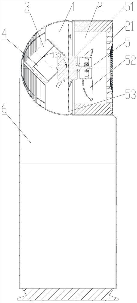
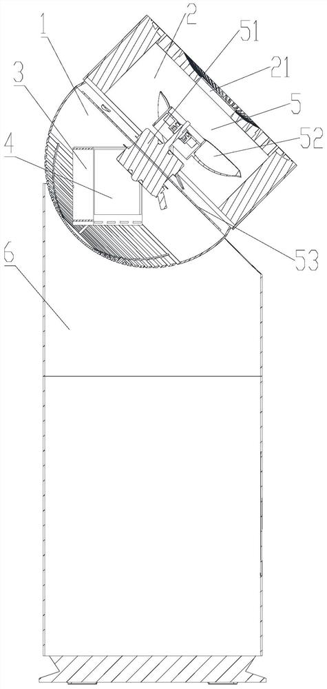
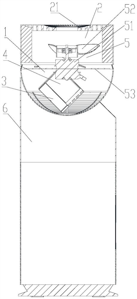
[0024] Such as figure 1 As shown, the machine head of the present invention includes a housing with an air duct, and the air inlet and air outlet of the air duct are respectively arranged on the opposite side walls of the housing. Along the air flow direction, the air duct is provided with a wet curtain assembly and The fan assembly 5, the wet curtain assembly is fixed on the inner wall of the housing, and the wet curtain assembly is inclined to the axial line of the air duct to ensure that when the housing shakes its head up and down, the wet curtain assembly is wetted at any angle and is in contact with the air. Contact to achieve the purpose of air supply and cooling.

[0025] The housing includes a front shell 2 and a rear shell 1...


PUM


Abstract

The invention discloses a machine head and a cooling fan. The machine head comprises a shell with an air channel, and an air inlet and an air outlet of the air channel are correspondingly formed in the opposite side walls of the shell; and a wet curtain assembly and a fan assembly are arranged in the air channel in the air circulation direction, the wet curtain assembly is fixed to the inner wall of the shell, and the wet curtain assembly is obliquely arranged relative to the axis of the air channel. According to the machine head, the wet curtain assembly is obliquely arranged relative to the axis of the air channel, so that in the head shaking process of the machine head, it is guaranteed that water flow can flow through a wet curtain and make contact with air when the machine head is at any angle, the purposes of air supply and cooling are achieved, and user experience is good.

Description

technical field [0001] The invention relates to the technical field of cooling fans, in particular to a machine head and a cooling fan. Background technique [0002] The cooling fan uses the evaporation of water to absorb heat and blow out cold air. The wet curtain is an important component of the cooling fan, which can increase the contact area and time between water and air, make the water absorb heat and evaporate, and effectively cool down. Under normal circumstances, the general cooling curtain is arranged on the cooling curtain support, and the cooling curtain support is fixed at the fan rear case or grille, and the cooling curtain then rotates with the fan shaking its head. [0003] With the wide application of cooling fans, circulation fans emerged as the times require. In addition to shaking their heads from side to side, circulation fans can also shake their heads up and down. If the wet curtain is in a vertical state, the air outlet direction of the fan that shak...

Claims


Application Information

Patent Timeline
11 May 2021
Publication
CN112781135A
IPC
F24F5/00; F24F6/00
CPC
F24F5/00; F24F6/00; F24F2006/001; Y02B30/54; F24F13/32; F24F5/0035; F24F6/04; F24F2221/38
Inventors
刘怡佐; 杨德豪