Spitting device for use in microwave oven

A microwave oven and piercing technology, applied in the field of piercing devices, can solve problems such as difficulty in accommodating various foods

Inactive Publication Date: 2003-11-19
SAMSUNG ELECTRONICS CO LTD
View PDF0 Cites 0 Cited by
  • Summary
  • Abstract
  • Description
  • Claims
  • Application Information

AI Technical Summary

Problems solved by technology

Therefore, it is difficult to accommodate various foods in the cooking chamber 2; and in order to cook many small foods, they can only be arranged in the lower area of ​​the cooking chamber 2

Method used


Image

  • Spitting device for use in microwave oven
  • Spitting device for use in microwave oven
  • Spitting device for use in microwave oven

Examples


Embodiment Construction

[0028] The present invention will be described below with reference to the accompanying drawings.

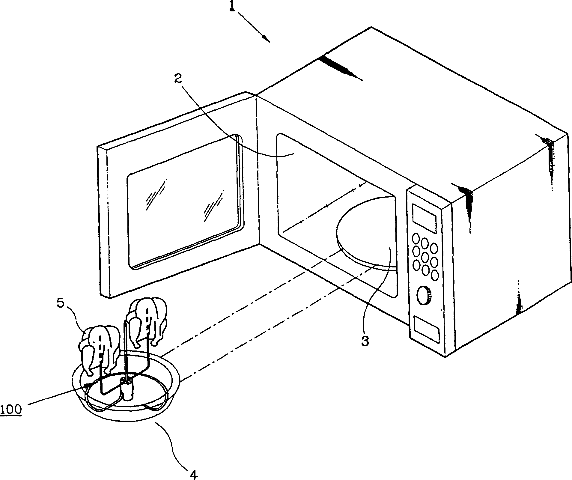
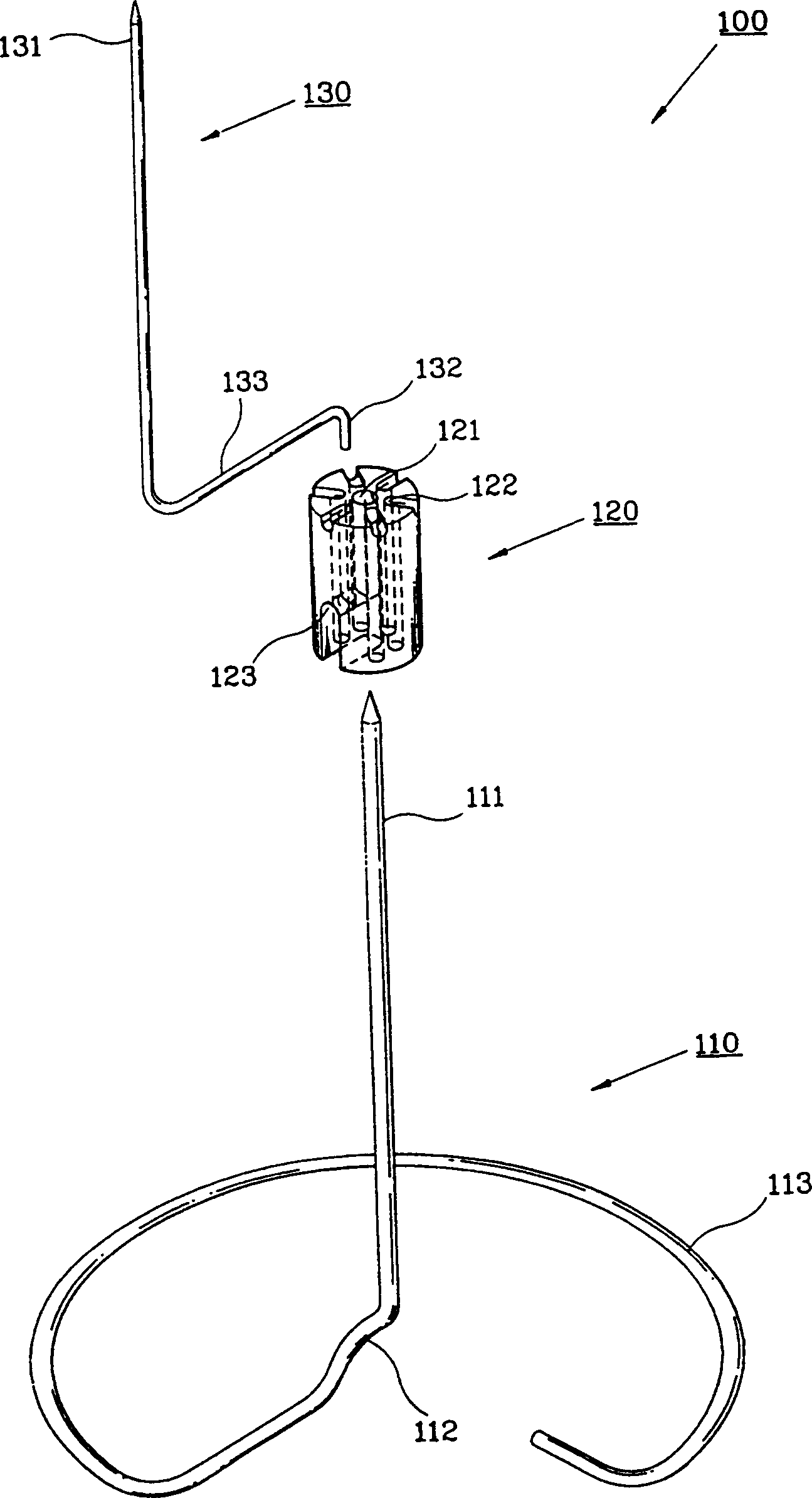
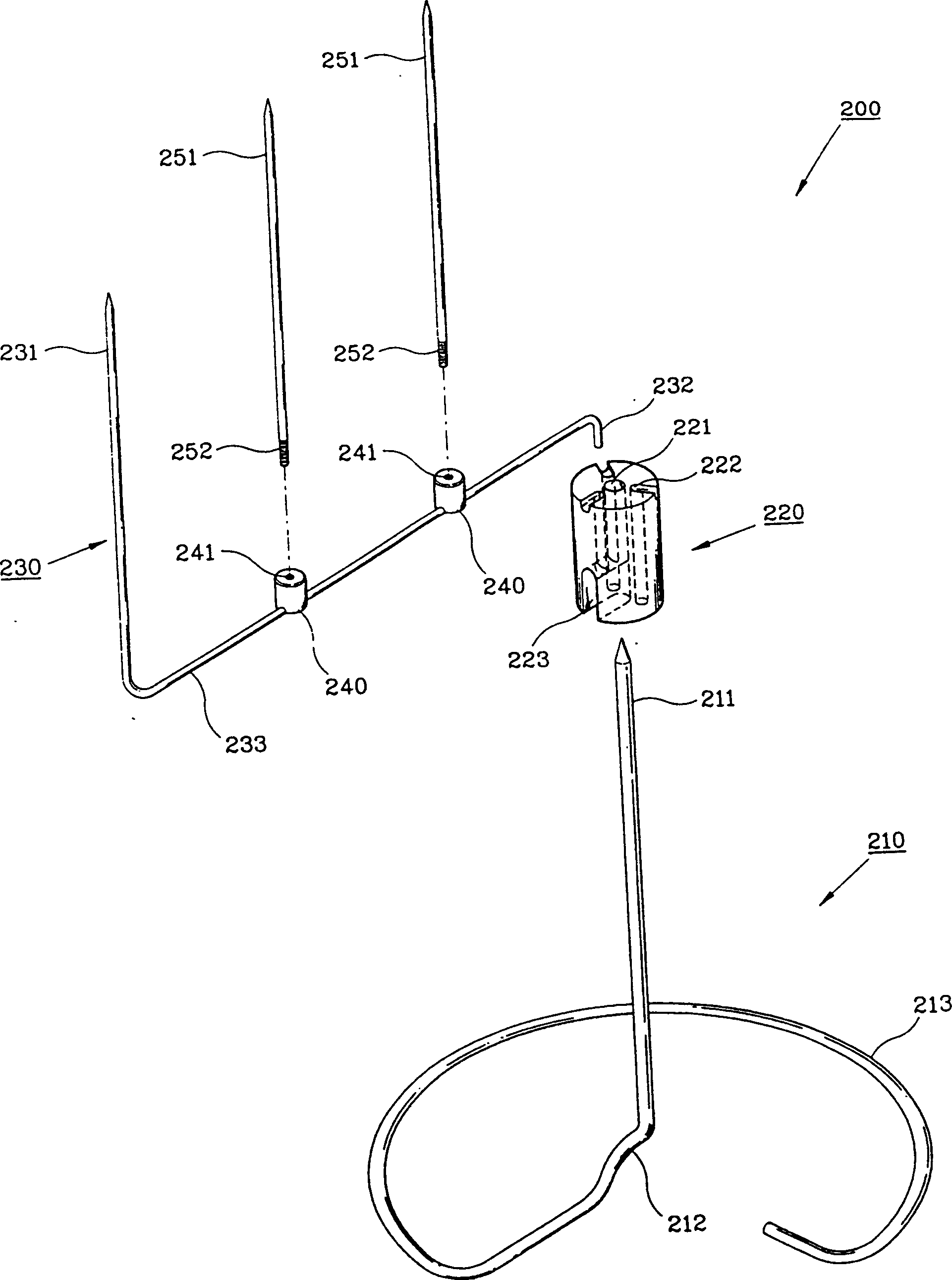
[0029] image 3 It is the piercing device 200 of the first embodiment of the present invention. The piercing device 200 includes: a central iron pick 210 for piercing food, a support 220 supported by the central iron pick 210 and a plurality of iron picks 230 detachably fixed on the support 220 . For the convenience of explanation, in figure 1 Only one iron pick 230 is shown in the figure; in fact, a plurality of iron picks 230 are radially placed on the support 220 .

[0030] The center iron pick member 210 is manufactured by bending a length of wire, and is composed of an upright center iron pick part 211 for piercing food and a support part 213 having the shape of a partial ring formed from the lower end of the center iron pick part 211. Extend and bend into an arc. The support portion 213 is used to support the center iron pick portion 211 so that it can maintain an upri...


PUM


Abstract

A device for spitting foodstuffs to be cooked in a cooking chamber of a microwave oven comprising a supporting member and many spit members supported by a fixing member. Each of the spit members has a fixing part engaged with the supporting member, a connection part extended outward in a radial direction from the fixing part, and many spit parts in parallel extended upward from the connection part. Thus, many a small foodstuff can be supported conveniently.

Description

technical field [0001] The present invention relates to a piercing device used in a microwave oven, and more particularly, to a piercing device having a plurality of iron pick portions for piercing food for roasting meat. Background technique [0002] figure 1 is a perspective view of a microwave oven with a conventional piercing device, figure 2 yes figure 1 An exploded perspective view of the piercing device shown. [0003] In a cooking chamber 2 of the microwave oven 1, a tray 3 rotated by a motor (not shown) is installed. When the user puts the food on the tray and turns on the microwave oven, microwaves are radiated onto the food to cook the food. [0004] Various means for supporting food in the cooking chamber 2 have been proposed. a tool is figure 1 and figure 2 Piercing device 100 is shown. When grilling meat on the tray 3 , the oil collecting tray 4 is used to receive the oil dripping from the food 5 , and the piercing device 100 is placed on the oil coll...

Claims


Application Information

Patent Timeline
IPC IPC(8): A47J36/02A47J37/04F24C7/02H05B6/64
CPCY10S99/14A47J37/04H05B6/6408A47J36/027
Inventor 金种宪赵在满金大来
Owner SAMSUNG ELECTRONICS CO LTD
Why Eureka
Try Eureka