Cabling rack for data center machine room, and construction method thereof

A data center and cable rack technology, applied in the field of cable racks, can solve problems such as general load-bearing capacity, easy shaking, and untargeted installation

Active Publication Date: 2021-05-14
奇信科技(广东)有限公司
8 Cites 0 Cited by

AI-Extracted Technical Summary

Problems solved by technology

[0003] The cable tray in the prior art has side panels, multiple cross arms and a bottom plate. The cables are not fixed on the multiple cross arms. The disadvantage is that the cables on the cross arms are placed in a mess, which is not convenient Subsequent maintenance, complex structure, cumbersome construction and installation, cumbersome disassembly when the cable needs to be repaired, time-consuming and laborious; and the load-bearing capacity is average, ...

Method used

For preventing problems such as accumulating dust after long-term use, make the generation of problems such as fi...

Abstract

The invention discloses a cabling rack for a data center machine room. The cabling rack comprises cabling protection cylinders, a cabling installation assembly and an adjusting and cable fixing device, and the adjusting and cable fixing device comprises an upper cable fixing device, a lower cable fixing device, a rubber cable placing device, an upper cable fixing nut, and a lower cable fixing nut. The invention relates to the technical field of cabling racks, and concretely provides the cabling rack for the data center machine room, and a construction method thereof. The cabling rack is characterized in that the upper cable fixing device and the lower cable fixing device are used for fixing a cable which is not changed frequently on the upper walls and the lower walls of the cabling protection cylinders, the cable which is changed frequently is placed into the rubber cable placing device, and connecting holes of the adjacent cabling protection cylinders are connected in a screwed mode through connecting bolts according to needs, the cabling rack is assembled into the required length and installed and used through the cabling installation assembly, in order to prevent the problems of fire and the like caused by dust accumulation and the like after long-time use, air blowing and dust removal can be carried out on the interior of the cabling protection cylinder through the vent holes, and the use safety of the device is guaranteed.

Application Domain

Electrical apparatus

Technology Topic

Structural engineeringElectrical and Electronics engineering +3

Image

  • Cabling rack for data center machine room, and construction method thereof
  • Cabling rack for data center machine room, and construction method thereof
  • Cabling rack for data center machine room, and construction method thereof

Examples

  • Experimental program(1)

Example Embodiment

[0024] The technical solutions in the embodiments of the present invention will be clearly and completely described below in conjunction with the accompanying drawings in the embodiments of the present invention. Obviously, the described embodiments are only some of the embodiments of the present invention, not all of them; based on The embodiments of the present invention and all other embodiments obtained by persons of ordinary skill in the art without making creative efforts belong to the protection scope of the present invention.
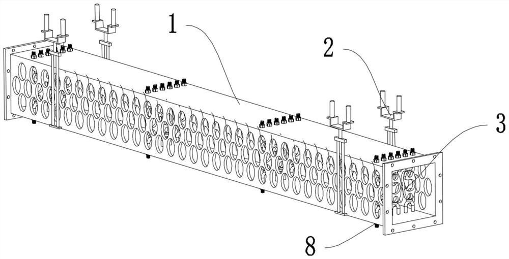
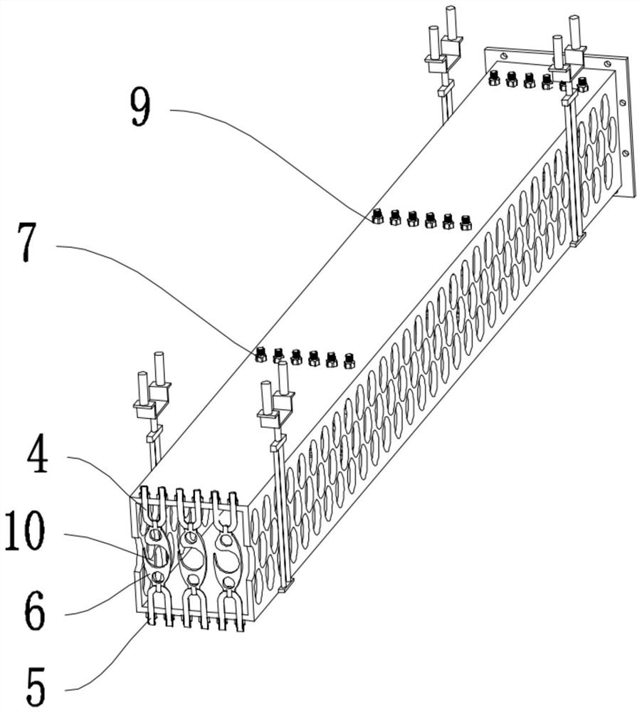
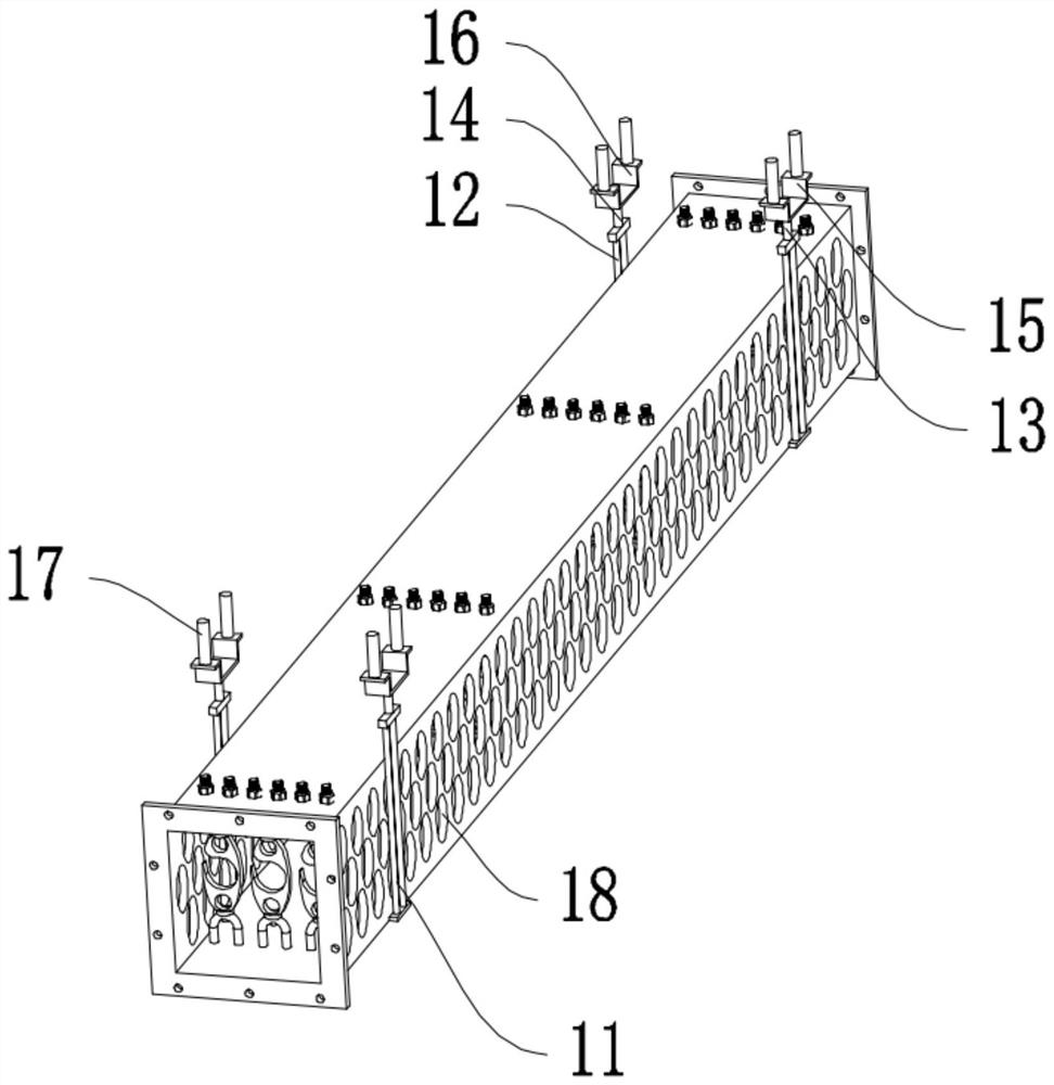
[0025] like Figure 1-4 As shown, the present invention is a cabling rack for a data center computer room, including a cabling protection tube 1, a cabling installation assembly 2, and a cable fixing device 3, and the cabling protection tube 1 is set in a hollow cavity with openings at both ends , the wiring installation assembly 2 is arranged on the side end of the wiring protection cylinder 1, and the adjusting and fixing device 3 is evenly arranged in the wiring protecting cylinder 1; the adjusting and fixing device 3 includes an upper fixing device 4 , the lower wire fixing device 5, the rubber wire setting device 6, the upper wire fixing nut 7 and the lower wire fixing nut 8, the top and the bottom of the wire routing protection cylinder 1 are provided with fixing wire holes 9, and the upper fixing wire The device 4 is set in a U shape, and the top of the upper wire fixing device 4 is set through the wire fixing hole 9 on the top of the wire protection tube 1, and the upper wire fixing device 4 is set on the top side of the wire routing protection tube 1. There is an upper wire fixing thread, the upper wire fixing nut 7 is screwed on the outside of the upper wire fixing thread, the lower wire fixing device 5 is arranged in an inverted U shape, and the bottom of the lower wire fixing device 5 penetrates the wire routing protection The wire fixing hole 9 at the bottom of the cylinder 1 is set, and the lower wire fixing device 5 is provided with a lower wire fixing thread on the bottom side of the wire routing protection cylinder 1, and the lower wire fixing nut 8 is screwed on the lower wire fixing thread The rubber wire setting device 6 is connected between the upper wire fixing device 4 and the lower wire fixing device 5. The rubber wire setting device 6 is arranged in an elliptical sheet shape and has collars on both sides. The sleeve The rings are respectively sleeved on the outside of the upper wire fixer 4 and the lower wire fixer 5, and an adjustment hole 10 is opened on the middle side of the rubber wire setter 6; the wiring installation assembly 2 includes a first support frame 11, The second supporting frame 12, the first connecting piece 13, the second connecting piece 14, the first mounting piece 15 and the second mounting piece 16, the first supporting frame 11 and the second supporting frame 12 are symmetrically connected and arranged on the line protection On the opposite side walls of the cylinder 1, the first connecting piece 13 is connected above the first supporting frame 11, the first mounting piece 15 is connected above the first connecting piece 13, and the second connecting piece 13 is connected above the first supporting frame 11. The piece 14 is connected above the second support frame 12, the second mounting piece 16 is connected above the second connecting piece 14, and the first mounting piece 15 and the second mounting piece 16 are arranged in an inverted a few shapes. Expansion bolts 17 are provided on the tops of the first mounting part 15 and the second mounting part 16 .
[0026] Wherein, vent holes 18 are uniformly formed on opposite side walls of the wire routing protection cylinder 1 .
[0027] Both sides of the wire protection tube 1 are provided with connection plates 19 , and connection holes 20 are uniformly formed around the connection plate 19 .
[0028] The connection holes 20 of the adjacent wiring protection cylinders 1 are connected by bolts 21 .
[0029] Two groups of the wiring installation components 2 are provided, and the two groups of the wiring installation components 2 are respectively arranged on the front and rear ends of the wiring protection cylinder 1 .
[0030] There are four sets of adjusting and fixing devices 3 in the wire routing protection cylinder 1 .
[0031] The upper and lower sides of the rubber wire setting device 6 are also provided with through holes.
[0032] The invention also discloses a construction method for a cable rack used in a data center computer room, which includes the following steps:
[0033] Step 1: First place the cables in the cable protection tube 1, use the upper and lower cable fixers 4 and 5 to fix the infrequently changing cables on the upper and lower walls of the cable protection tube 1, and then Use the upper wire fixing nut 7 to fix the upper wire fixing device 4, and use the lower wire fixing nut 8 to fix the lower wire fixing device 5;
[0034] Step 2: Put the cables that change frequently into the rubber wire guide 6, so that the cables that change frequently pass through the adjustment holes 10 in the cable protection tube 1 and set them;
[0035] Step 3: As required, connect the connection holes 20 of the adjacent wiring protection tubes 1 with the connection bolts 21, and splice them into required lengths;
[0036]Step 4: Finally, the cable protection tube 1 can be installed and used through the cable installation component 2.
[0037] In order to prevent problems such as dust accumulation after long-term use from causing problems such as fires, the inside of the wiring protection tube 1 can be blown and cleaned through the vent hole 18 to ensure the safety of the device.
[0038] The present invention and its implementations have been described above, and this description is not limiting. What is shown in the drawings is only one of the implementations of the present invention, and the actual structure is not limited thereto. All in all, if a person of ordinary skill in the art is inspired by it, and without departing from the inventive concept of the present invention, without creatively designing a structure and an embodiment similar to the technical solution, it shall fall within the scope of protection of the present invention.
[0039] It should be noted that in this article, relational terms such as first and second are only used to distinguish one entity or operation from another entity or operation, and do not necessarily require or imply that there is a relationship between these entities or operations. There is no such actual relationship or order between them. Furthermore, the term "comprises", "comprises" or any other variation thereof is intended to cover a non-exclusive inclusion such that a process, method, article or apparatus comprising a set of elements includes not only those elements, but also includes elements not expressly listed. other elements of or also include elements inherent in such a process, method, article, or device.

PUM

no PUM

Description & Claims & Application Information

We can also present the details of the Description, Claims and Application information to help users get a comprehensive understanding of the technical details of the patent, such as background art, summary of invention, brief description of drawings, description of embodiments, and other original content. On the other hand, users can also determine the specific scope of protection of the technology through the list of claims; as well as understand the changes in the life cycle of the technology with the presentation of the patent timeline. Login to view more.
Why Eureka
Try Eureka