
a dispenser

A dispenser and faucet technology, which is used in wellbore/well components, production fluids, earth-moving drilling, etc., can solve the problems of poor deployment accuracy, large workload, and increased workload, and achieve accurate and calculable metering flow. , High docking success rate and the effect of reducing workload

Active Publication Date: 2021-11-09
DAQING TIANDEZHONG PETROLEUM SCI & TECH CO LTD
View PDF9 Cites 0 Cited by
  • Summary
  • Abstract
  • Description
  • Claims
  • Application Information

AI Technical Summary

Problems solved by technology

[0002] In recent years, with the development and improvement of bridge eccentric and conventional eccentric injection technology, it has been widely used in major oil fields. According to the loss curve of the mouth, roughly select a water nozzle with a fixed size, put it into the plug, put the plug into the water distributor with a dropper, and then test the actual water injection volume of each layer with a flow meter. If the actual injection If the amount of water does not meet the requirements, it is necessary to remove the plug and the faucet, replace the faucet and then put it into the water distributor, and repeat this until the water injection amount of the layer meets the requirements. The quantity is large, and the success rate of instrument docking is low. At the same time, the size of the faucet is discontinuous, and the deployment accuracy is poor;
[0003] Although the ordinary bridge-type concentric dispenser overcomes the above-mentioned defects, the test deployment operation and the packer seal inspection operation must be tested separately by testing equipment, and they cannot be operated at the same time, which increases the workload and affects work efficiency.

Method used


Image

  • a dispenser
  • a dispenser
  • a dispenser

Examples


Embodiment Construction

[0015] The present invention will be further described below with reference to the accompanying drawings:

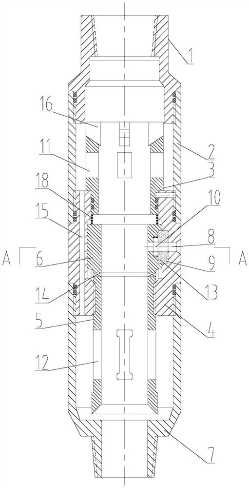
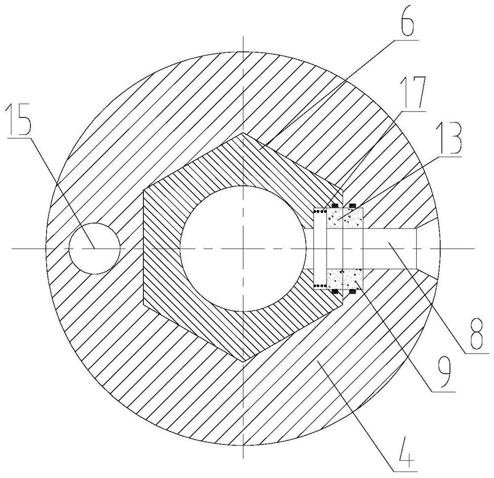
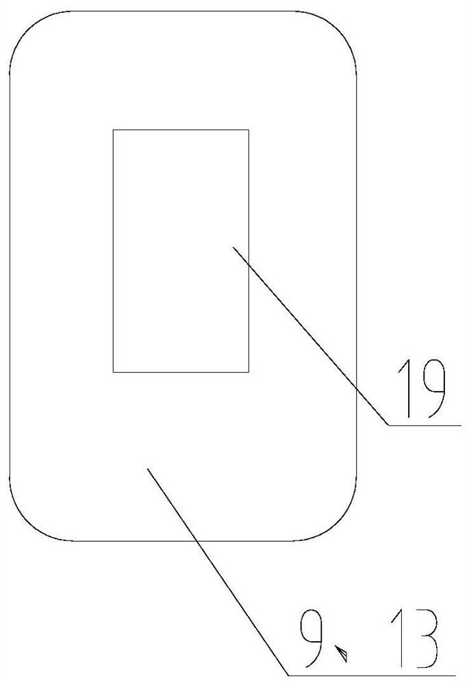
[0016] Depend on figure 1 Combine Figure 2 ~ 3 Shown, with injection, comprising an upper joint, a lower end of the outer connection joint casing 2, the lower end of the inner casing 2 is connected fixed tap 4, the connector 7 is connected the lower end of the fixed outer nozzle 4 is fixed to the central nozzle 4 radial wall of the outlet opening 8 of the sleeve, nozzle 4 is fixed inside the upper end of the lower end of rotary drum positioned outside relieve rotation 3, the lower end of the fixed nozzle 4 by a screw screwed active elevating pipe 5, the elevating pipe 5 side activities through the planar nozzle 14 is connected to a bearing 6, a lower portion of the elevating pipe 5 is provided with an adjustment slot 12;

[0017] 6 Tap activities hexagonal pillar shape, the movable nozzle 6 connected to a fixed mating hexagonal slot nozzle gap 4, the movable nozzle 6 and the...


PUM


Abstract

The present invention proposes a dispenser. The utility model relates to the technical field of oil field downhole tools. On the plane opposite to the liquid outlet and the water outlet, the movable nozzle is provided with a ceramic sheet II, and the fixed nozzle is provided with a ceramic sheet I. Both the ceramic sheet I and the ceramic sheet II have rectangular metering holes in the transverse direction, and the ceramic sheet I A spring I is arranged between the movable faucet. The invention has the following beneficial effects: by setting the lifting pipe and the movable water nozzle, the downhole positioning and docking of the injector and the bridge-type concentric seal inspection and adjustment integrated tester and the adjustment of water volume can be realized to meet the stratification of highly inclined wells and deep wells The need for water distribution; the unique structural design of the rectangular metering hole, the metering flow is accurate and can be calculated, cooperate with the bridge-type concentric testing and sealing integrated testing instrument, the next instrument can realize the simultaneous operation of water injection volume adjustment and packer sealing inspection, only It is necessary to drive the movable water nozzle up and down to realize the adjustment of the water injection volume. The adjustment accuracy is high, and there is no problem of water nozzle throwing and fishing, which reduces the workload and improves the efficiency.

Description

Technical field: [0001] The present invention relates to oil field downhole tools technical field, in particular with a dispenser. Background technique: [0002] In recent years, with the bridge and conventional eccentric eccentric dispensing technology development and improvement in the major oil fields have been increasingly wide range of application, during the test deployment, according to the water with various oil and water loss curve mouth, the coarse tap select a fixed size, which is blocked into the vessel, with the cast fishing will occluder into water distributor, the water injection flow meter and the actual testing of each layer, if the actual injection mainly the water, and the need to remove nozzle clogging, to replace the nozzle and then into the water distribution, and so forth, until the layer reaches the water injection requirements, so that, again and pulling the replacement nozzle, working large, the instrument docking success rate, while the size of the nozz...

Claims


Application Information

Patent Timeline
Patent Type & Authority Patents(China)
IPC IPC(8): E21B43/20E21B43/14
CPCE21B43/14E21B43/20
Inventor 张淞源张虎
Owner DAQING TIANDEZHONG PETROLEUM SCI & TECH CO LTD
Learn More