Square sheet stamping equipment for hardware

A stamping equipment and square technology, which is applied in the field of square sheet stamping equipment for hardware, can solve problems such as easy cutting of unqualified square iron sheets

Pending Publication Date: 2021-05-28
舒李兰
View PDF0 Cites 2 Cited by
  • Summary
  • Abstract
  • Description
  • Claims
  • Application Information

AI Technical Summary

Problems solved by technology

[0004] In order to overcome the shortcomings of the existing technology that the iron sheet needs to be manually pulled, it is easy to cut out unqualified square iron sheets, and the cut iron sheet needs to be manually rolled up, the technical...

Method used


Image

  • Square sheet stamping equipment for hardware
  • Square sheet stamping equipment for hardware
  • Square sheet stamping equipment for hardware

Examples


Embodiment 1

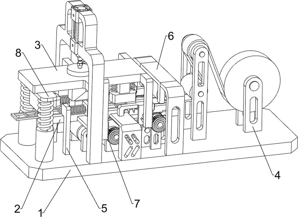
[0029] A square sheet stamping equipment for hardware, such as figure 1 , figure 2 and image 3 As shown, it includes a bottom plate 1, a stamping platform 2, a stamping mechanism 3 and a feeding mechanism 4, a stamping platform 2 is provided on the left side of the top of the bottom plate 1, a stamping mechanism 3 is provided on the left side of the top of the bottom plate 1, and a stamping mechanism 3 is provided on the top right side of the bottom plate 1. Feeding mechanism4.

[0030] When people need to use this equipment, first people will take off the 4 parts of the feeding mechanism, then put the iron sheet roll on the 4 parts of the feeding mechanism, then reset the 4 parts of the feeding mechanism, and bypass the head end of the iron sheet The feeding mechanism 4 moves to the stamping platform 2 below the stamping mechanism 3, and then people can start the stamping mechanism 3. First, the stamping mechanism 3 moves downward, and when the stamping mechanism 3 moves ...

Embodiment 2

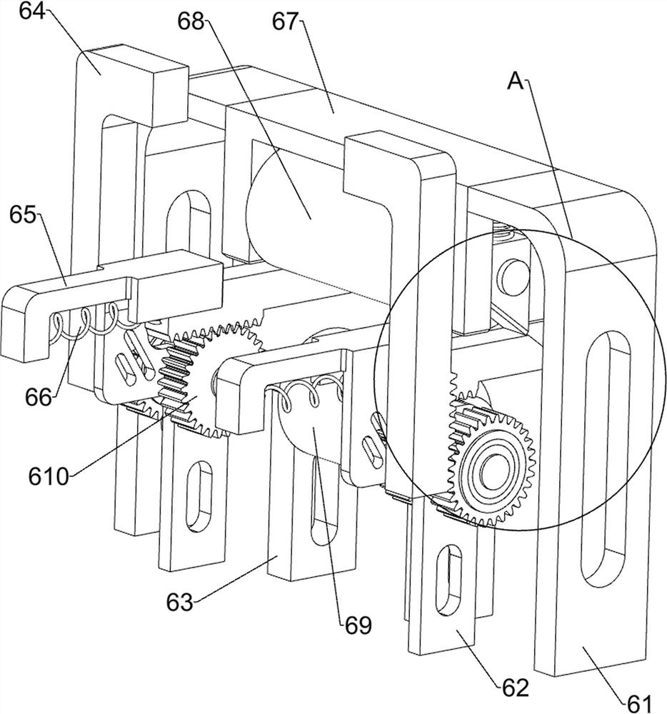
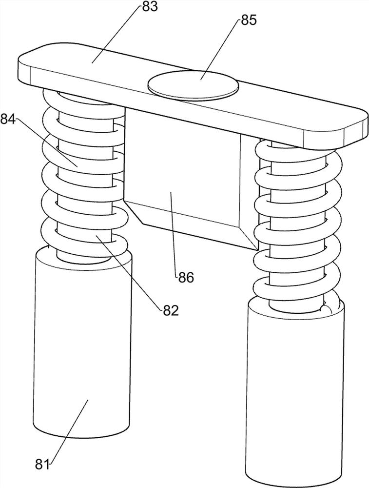
[0035] On the basis of Example 1, such as figure 1 , Figure 4 , Figure 5 , Image 6 , Figure 7 and Figure 8 As shown, it also includes a pulling mechanism 5, and the pulling mechanism 5 includes a pulling support frame 51, a guide post spring 52, a pulling guide post 53, an opening slider 54, a slotting slider 55, and a first wedge block 56 , the second wedge-shaped block 57, the pulling material spring 58 and the pulling material wedge-shaped block 59, the left side of the bottom plate 1 top is symmetrically provided with a pulling material support frame 51, and the pulling material support frame 51 is equipped with a guide post spring 52, and the pulling material support frame 51 is provided with pulling material guide post 53, and guide post spring 52 is enclosed within pulling material guide post 53 outsides, and drawing material guide post 53 is all slidingly provided with perforated slide block 54, and perforated slide block 54 is provided with Slotted slider 55...


PUM


Abstract

The invention relates to stamping equipment, in particular to square sheet stamping equipment for hardware. According to the square sheet stamping equipment for the hardware, an iron sheet can be automatically pulled, the cut iron sheet can be automatically wound, and people can conveniently collect the square iron sheet. The square sheet stamping equipment for the hardware comprises a bottom plate, a stamping mechanism and a feeding mechanism, wherein a stamping platform is arranged on the bottom plate, the stamping mechanism is arranged on the bottom plate, and the feeding mechanism is arranged on the bottom plate. According to the equipment, the iron sheet is placed through the feeding mechanism, then the iron sheet is stamped in combination with the stamping mechanism, and therefore the square iron sheet is efficiently manufactured; and through cooperation between a material pulling mechanism and the stamping mechanism, the iron sheet is automatically pulled leftwards, and in this way, the iron sheet does not need to be pulled manually.

Description

technical field [0001] The invention relates to a punching equipment, in particular to a square piece punching equipment for hardware. Background technique [0002] In the production and processing of some machines, square iron sheets are usually used. Square iron sheets are mostly cut from iron sheets. First, people place the iron sheet on the workbench, and then start the stamping mechanism to stamp and cut the iron sheet. Whenever one part of the iron sheet is cut, people need to manually pull the iron sheet to make the stamping mechanism cut the next part of the iron sheet. In this way, it is necessary to pay attention to the cutting situation of the iron sheet at all times, and it is easy to cut unqualified square iron sheet if you do not pay attention. If the unqualified square iron sheet is mixed with the qualified iron sheet, then people need to pick out the unqualified iron sheet in the later stage, which is inconvenient, and the winding of the cut iron sheet also n...

Claims


Application Information

Patent Timeline
IPC IPC(8): B21D22/02B21D43/00B21D43/04B21C47/18B21D28/02B21D35/00
CPCB21C47/18B21D22/02B21D28/02B21D35/002B21D43/003B21D43/04
Inventor 舒李兰
Owner 舒李兰
Why Eureka
Try Eureka