
Hydraulic boring head for machining engine cylinder cover seat ring guide pipe

A technology for engine cylinder heads and seat rings, which is applied to boring heads, metal processing equipment, manufacturing tools, etc., and can solve problems such as inconsistent tool travel standards in conduit holes, large tool jumps, and unstable tool processing processes.

Active Publication Date: 2021-05-28
BEIJING FOTON CUMMINS ENGINE
View PDF6 Cites 0 Cited by
  • Summary
  • Abstract
  • Description
  • Claims
  • Application Information

AI Technical Summary

Problems solved by technology

The reasons are as follows: 1) The tool is fixed with side pressure screws, which make the tool deviate from the rotation center of the mandrel, resulting in large tool jump; Due to the coaxiality problem between multiple constraining surfaces, the traveling reference of the conduit hole tool will be inconsistent; 3) The clamping part between the tool and the tool is too long, resulting in the tool being extremely unstable during the machining process

Method used

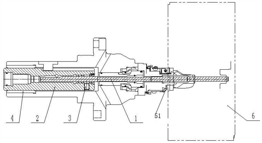
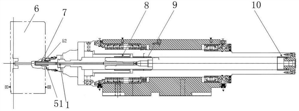
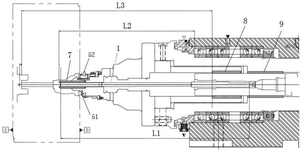

Image

  • Hydraulic boring head for machining engine cylinder cover seat ring guide pipe
  • Hydraulic boring head for machining engine cylinder cover seat ring guide pipe
  • Hydraulic boring head for machining engine cylinder cover seat ring guide pipe

Examples


Embodiment Construction

[0035]The present invention will be further described below with reference to the accompanying drawings.

[0036]By the followingFigure 1-3The process of the existing seat hole and catheter holes will be described.

[0037]As described in the background art, the engine cylinder head is irregularly, the roundness does not meet the standard, whose reasons have the following three points: 1) Tools are fixed, side pressure screws The screw causes the tool to deviate from the center of the mandrel, causing the tool beating to be large; 2) The catheter hole tool is much constrained during the feed, and the plurality of constrained faces will cause the tube hole tool to travel Do not unify; 3) The clamping part of the tool and the tool is too long, causing the tool extremely unstable during processing. The specific reasons for the above three points are described in detail below:

[0038]1) The tool is fixed by a side pressure screw, and the side pressure screw causes the tool to deviate from the c...


PUM


Abstract

The invention provides a boring head used for clamping a cutter for machining an engine cylinder cover. The boring head comprises a mandrel, a cutter guide sleeve and a hydraulic clamping mechanism, wherein the cutter guide sleeve is used for enabling the cutter to be arranged in a penetrating mode and limiting the cutter, the hydraulic clamping mechanism is contained in the center of the mandrel and is used for clamping the cutter, the mandrel rotates to feed to drive the hydraulic clamping mechanism to rotate to feed, and therefore the cutter is driven to rotate to feed in the cutter guide sleeve to machine the engine cylinder cover. According to the boring head, the hydraulic mechanism is adopted for fixing the cutter, and therefore the problem that in the prior art, the cutter jumps greatly due to the fact that the cutter is fixed by adopting a side pressing screw can be solved; and in addition, the boring head is only provided with one mandrel guide sleeve, and therefore the problem that in the prior art, the advancing datum of the cutter is not uniform due to the fact that a plurality of mandrel guide sleeves are adopted can be solved.

Description

Technical field[0001]The present invention relates to the field of engine manufacturing techniques, and more particularly to a hydraulic stick for machining the engine cylinder head.Background technique[0002]In the process of the engine cylinder cover seat and the conduit hole, in order to ensure the beating requirements of the seat hole and the catheter hole (generally required the beating degree of 0.075 mm), the seat hole boring knife and catheter hole tool are typically designed in one On the mandrel, the seat hole and the catheter hole are machined once to ensure the concentricity of the seat hole and the catheter hole, thereby ensuring the sealing of the valve to the cylinder combustion chamber. However, this design method requires a higher tool structure, which will increase the difficulty of manufacturing in the tool.[0003]In the process of the existing engine cylinder seat rings and catheter holes, it is to design the seat hole boring knife and the catheter hole tool on one...

Claims


Application Information

Patent Timeline
Patent Type & Authority Applications(China)
IPC IPC(8): B23B29/03B23B41/00
CPCB23B29/03B23B41/00
Inventor 孙波张浩钧赵河
Owner BEIJING FOTON CUMMINS ENGINE
Learn More