
A hydraulic boring head for machining conduits of engine cylinder head seat rings

A technology for engine cylinder heads and seat rings, which is applied in boring heads, metal processing equipment, manufacturing tools, etc., and can solve problems such as long tool and tool clamping parts, non-uniform guidelines for tool travel in conduit holes, and unstable tool processing processes, etc.

Active Publication Date: 2022-03-01
BEIJING FOTON CUMMINS ENGINE
View PDF0 Cites 0 Cited by
  • Summary
  • Abstract
  • Description
  • Claims
  • Application Information

AI Technical Summary

Problems solved by technology

The reasons are as follows: 1) The tool is fixed with side pressure screws, which make the tool deviate from the rotation center of the mandrel, resulting in large tool jump; Due to the coaxiality problem between multiple constraining surfaces, the traveling reference of the conduit hole tool will be inconsistent; 3) The clamping part between the tool and the tool is too long, resulting in the tool being extremely unstable during the machining process

Method used


Image

  • A hydraulic boring head for machining conduits of engine cylinder head seat rings
  • A hydraulic boring head for machining conduits of engine cylinder head seat rings
  • A hydraulic boring head for machining conduits of engine cylinder head seat rings

Examples


Embodiment Construction

[0035] The present invention will be further described below in conjunction with accompanying drawing.

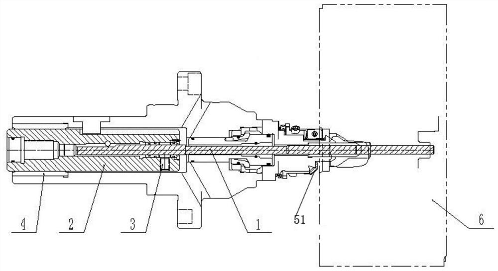
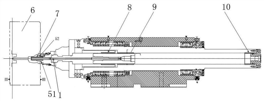
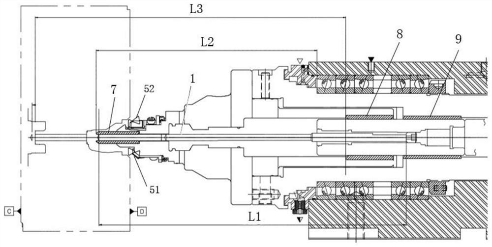
[0036] Attached below Figure 1-3 The existing processing methods of the seat ring hole and the guide hole will be described.

[0037] As described in the background technology, the conduit hole or the seat ring hole of the engine cylinder head is irregular and the roundness does not meet the standard. The reasons are as follows: 1) The cutter is fixed by a lateral pressure screw, The screw makes the tool deviate from the center of rotation of the mandrel, resulting in a large tool jump; 2) There are many constraining surfaces for the conduit hole cutter during the feeding process, and the coaxiality problem between multiple constraint surfaces will make the travel benchmark of the conduit hole cutter Not uniform; 3) The clamping part between the tool and the tool is too long, which makes the tool extremely unstable during processing. The specific reasons for the above th...


PUM


Abstract

The present application provides a boring head, which is used for clamping a tool for processing an engine cylinder head. The boring head includes a mandrel; a tool guide sleeve, which is used to pass through the tool and limit the position of the tool; Clamping mechanism, which is housed in the center of the mandrel, is used to clamp the tool, and the rotation of the mandrel drives the hydraulic clamping mechanism to rotate and feed, thereby driving the tool to rotate in the tool guide sleeve Feed to machine engine cylinder heads. The present application adopts a hydraulic mechanism to fix the tool, which solves the problem of large jump of the tool caused by fixing the tool with side pressure screws in the prior art. Moreover, the boring head of the present application is provided with only one mandrel guide bush, which solves the problem of non-uniformity of the tool travel standard caused by the use of multiple mandrel guide bushes in the prior art.

Description

technical field [0001] The invention relates to the technical field of engine manufacturing, and more particularly, relates to a hydraulic boring head for machining a conduit of a seat ring of an engine cylinder head. Background technique [0002] In the machining of the engine cylinder head seat ring hole and conduit hole, in order to ensure the runout requirements of the seat ring hole and conduit hole (generally require the runout within 0.075mm), the seat ring hole boring tool and the conduit hole cutter are usually designed in one On the mandrel, the seat ring hole and the conduit hole are processed and formed at one time to ensure the concentricity of the seat ring hole and the conduit hole, thereby ensuring the sealing of the valve to the cylinder combustion chamber. However, this design method has higher requirements on the tool structure, which will increase the difficulty of tool manufacturing. [0003] In the existing processing of the seat ring hole and the guid...

Claims


Application Information

Patent Timeline
Patent Type & Authority Patents(China)
IPC IPC(8): B23B29/03B23B41/00
CPCB23B29/03B23B41/00
Inventor 孙波张浩钧赵河
Owner BEIJING FOTON CUMMINS ENGINE
Learn More