a range hood

A technology for range hoods and fans, which is used in the removal of range hoods, household stoves/stoves, heating methods, etc., can solve the problems of inconvenient cleaning, coating peeling, and inconvenient spraying of plastic coatings, achieving a wide range of cleaning and easy production and implementation. Effect

Active Publication Date: 2022-04-19
NINGBO FOTILE KITCHEN WARE CO LTD
View PDF11 Cites 0 Cited by
  • Summary
  • Abstract
  • Description
  • Claims
  • Application Information

AI Technical Summary

Problems solved by technology

There is some inconvenience in spraying plastic coating
[0006] Therefore, although the method of coating can facilitate the cleaning of range hoods to a certain extent, there are still defects that the coating will fall off after being wiped many times with a rag, and that it is inconvenient to spray the coating.
And it is still not easy to clean places without coating such as stoves and cabinets

Method used


Image

  • a range hood
  • a range hood
  • a range hood

Examples


Embodiment 1

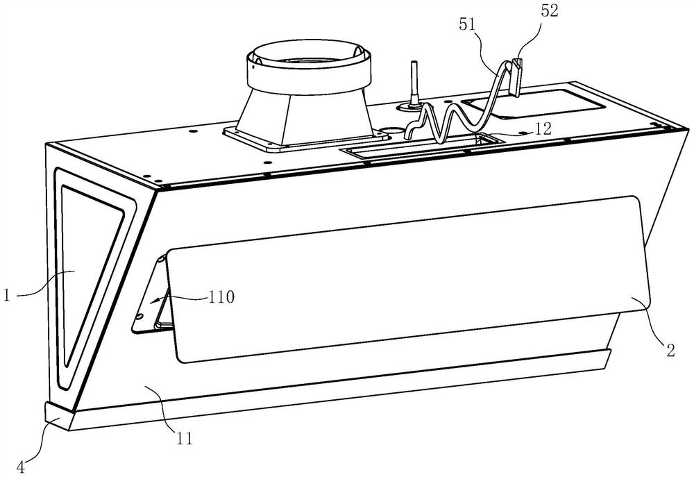
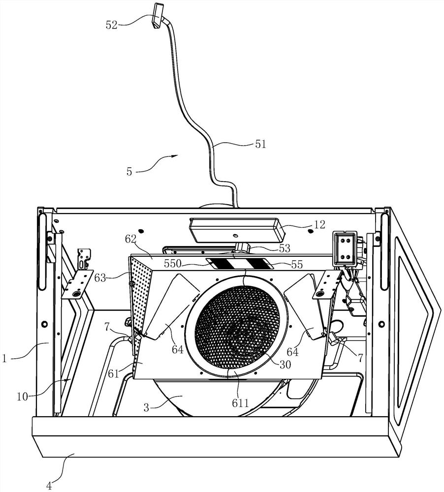
[0043]Such as Figure 1-7 Shown is a preferred embodiment 1 of a range hood of the present invention, which includes a housing 1 , a smoke baffle 2 , a fan 3 , an oil cup 4 , an oil suction assembly 5 , and an oil guide frame 6 .

[0044] Wherein, a smoke inlet chamber 10 is formed inside the housing 1, a panel 11 is provided on the front side of the housing 1, and a smoke inlet 110 communicating with the smoke inlet chamber 10 is opened on the panel 11 (the range hood in this embodiment is Side-suction range hoods, of course, can also be European-style range hoods). The smoke baffle 2 is arranged on the panel 11 to open and close the smoke inlet 110. The structure of the smoke baffle 2, the connection method with the panel 11 and the way of driving the smoke baffle 2 to open and close the smoke inlet 110 can refer to existing The technical design will not be repeated here. The above-mentioned fan 3 is arranged in the casing 1 , and the air inlet 30 of the fan 3 is arranged ...

Embodiment 2

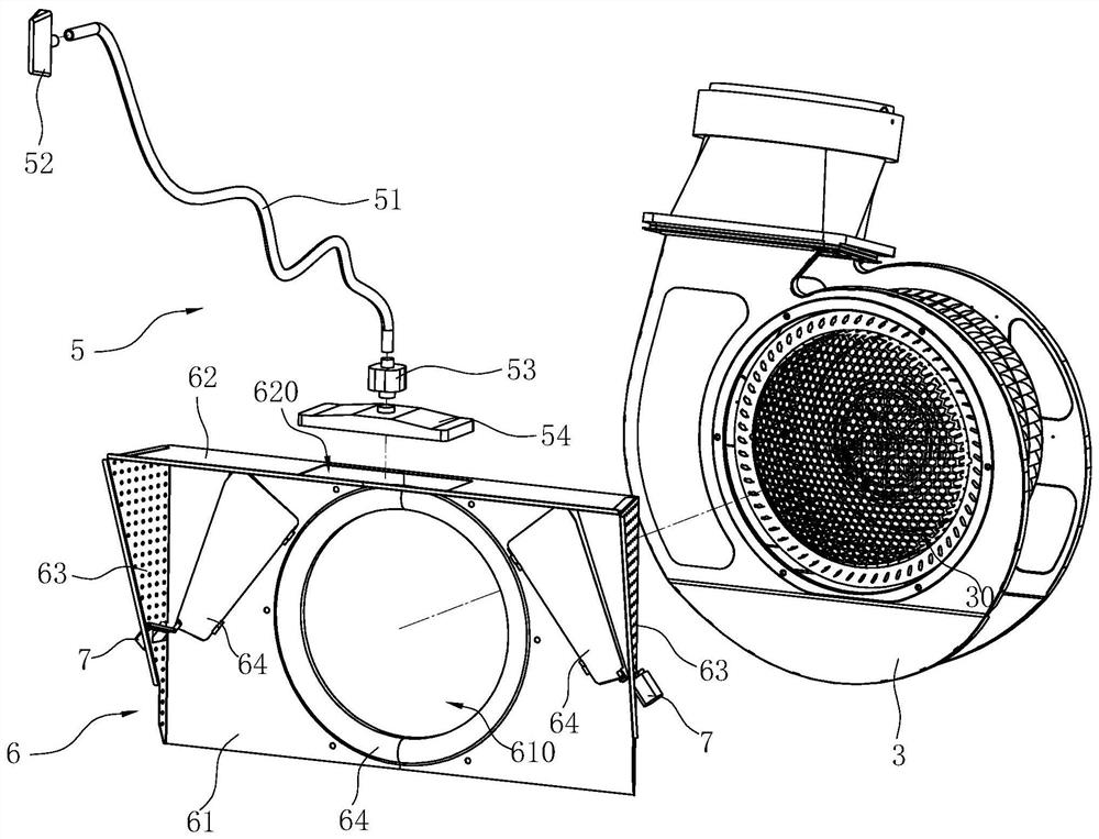
[0051] Such as Figure 8 As shown, it is a preferred embodiment 2 of a range hood of the present invention. This range hood is basically the same as Embodiment 1, the difference is that in this embodiment, each baffle plate 64 is opposite to each group of grill holes 550, and each The angle α between the baffle plate 64 and the vertical plane is greater than the angle β between the corresponding grid holes and the vertical plane; the projection of each group of grid holes 550 on the horizontal plane falls into the corresponding baffle plate 64 at within the projection on the horizontal plane. So that the oil from the grill hole 550 can flow to the baffle 64 and flow down along the baffle 64 to prevent the oil from entering the fan 3 .

Embodiment 3

[0053] Such as Figures 9 to 11 As shown, it is the third preferred embodiment of a range hood of the present invention, the range hood is basically the same as the first embodiment, the difference is that there is no baffle plate and grille in this embodiment, in this embodiment, Below the dirt inlet hole 620, there is a deflector 8 for guiding the oil to the front wall of the vertical plate 61; Afterwards, it gradually inclines downward, and the rear end edge of the deflector 8 abuts against the front wall of the vertical plate 61 .


PUM


Abstract

A range hood, comprising a housing (1), a fan (3) and an oil cup (4) disposed in the housing (1), the housing (1) is formed with a smoke inlet chamber (10), The casing (1) is provided with a smoke inlet (110) communicating with the smoke inlet chamber (10), and the smoke inlet is arranged to be openable or closed, and the air inlet of the fan (3) (30) communicates with the smoke inlet chamber (10); the oil cup (4) is located under the housing and communicates with the smoke inlet chamber (10); it is characterized in that it also includes a suction pipe (51) , the first end of the suction pipe (51) communicates with the smoke inlet chamber (10), the second end is a free end protruding from the casing (1), and the free end has a dirt suction pipe for oil suction. mouth. Compared with the prior art, the range hood of the invention can realize non-contact cleaning.

Description

technical field [0001] The invention belongs to the technical field of kitchen appliances, and in particular relates to a range hood. Background technique [0002] Existing range hoods, such as the invention patent "A Side Suction Range Hood" with the patent number ZL201910567583.9 (the authorized announcement number is CN110375354B), and the utility model patent "A Range Hood" with the patent number ZL201821959688.6 (The authorized announcement number is CN209295241U), the invention patent of ZL201910686483.8 "A Drip Oil Range Hood" (authorized announcement number is CN110397971B) and other disclosed structures use the suction of the centrifugal fan to discharge the oil fumes. [0003] During the cooking process in the kitchen, a lot of oil fume will be generated. Most of the oil fume will be sucked away by the range hood, and a small part will adhere to the outer surface of the range hood, the stove and nearby cabinets. In order to keep the kitchen clean and tidy, users n...

Claims


Application Information

Patent Timeline
Patent Type & Authority Patents(China)
IPC IPC(8): F24C15/20
CPCF24C15/20F24C15/2035
Inventor 梁齐齐
Owner NINGBO FOTILE KITCHEN WARE CO LTD
Why Eureka
Try Eureka