Load shedding method and device of stability control device for direct-current power prompt drop and terminal equipment

A technology of stabilizing control device and DC power, which is applied in the direction of circuit device, emergency treatment AC circuit layout, AC network circuit, etc. It can solve the problem that the stabilizing control device cannot operate correctly and reliably to shed load at the exit, and achieve the elimination of safety and stability hidden dangers , Improve the effect of adaptability and reliability

Active Publication Date: 2021-05-28
ELECTRIC POWER RESEARCH INSTITUTE, CHINA SOUTHERN POWER GRID CO LTD
View PDF6 Cites 0 Cited by
  • Summary
  • Abstract
  • Description
  • Claims
  • Application Information

AI Technical Summary

Problems solved by technology

[0007] The embodiment of the present invention provides a load shedding method, device and terminal equipment for a DC power rapid drop stabilization control device, which are used to solve the existing DC tran

Method used


Image

  • Load shedding method and device of stability control device for direct-current power prompt drop and terminal equipment
  • Load shedding method and device of stability control device for direct-current power prompt drop and terminal equipment

Examples


Example Embodiment

[0039] Embodiment one:

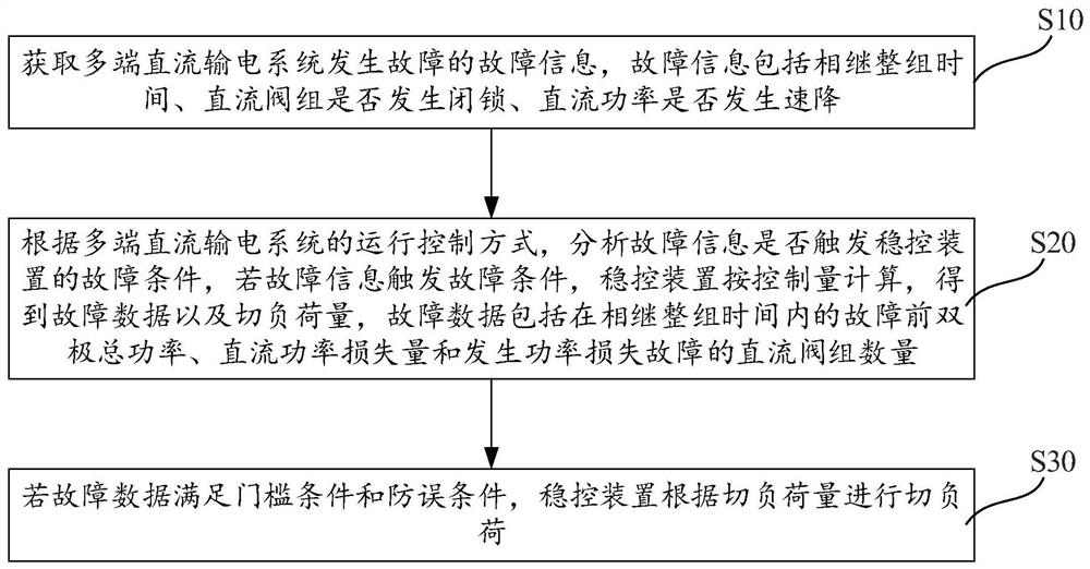
[0040] figure 1 It is a flow chart of the steps of the load shedding method of the DC power droop stabilization control device described in the embodiment of the present invention.

[0041] like figure 1 As shown, the embodiment of the present invention provides a load shedding method for a DC power rapid drop stabilization control device, which is applied to an UHV multi-terminal DC transmission system and includes the following steps:

[0042] S10. Obtain the fault information of the fault of the UHV multi-terminal direct current transmission system, the fault information includes the time of the whole group successively, whether the DC valve group is blocked, and whether the DC power drops rapidly;

[0043] S20. According to the operation control mode of the UHV multi-terminal direct current transmission system, analyze whether the fault information triggers the fault condition of the stability control device. The data include the bipolar total p...

Example Embodiment

[0059] Embodiment two:

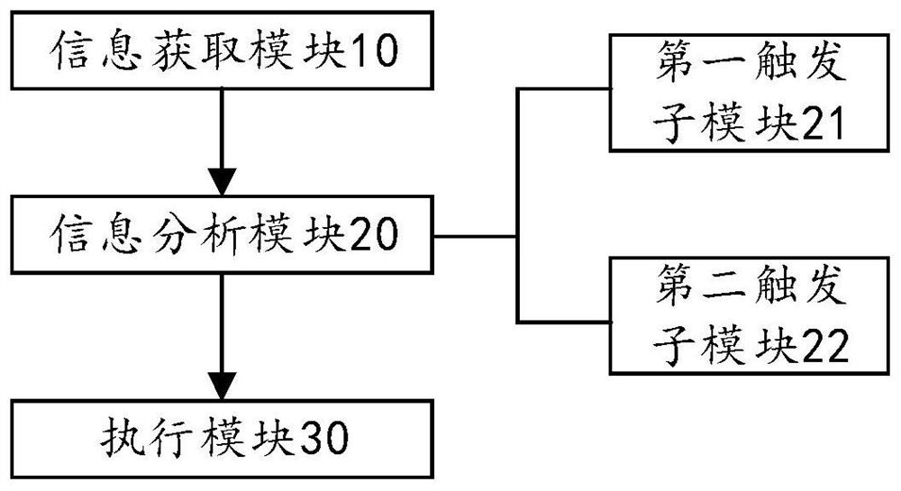
[0060] figure 2 It is a frame diagram of the DC valve group failure shut-off device of the stability control device described in the embodiment of the present invention.

[0061] like figure 2 As shown, the embodiment of the present invention also provides a DC valve group failure shutdown device for a stability control device, which is applied to an UHV multi-terminal DC transmission system, and includes an information acquisition module 10, an information analysis module 20, and an execution module 30;

[0062] The information acquisition module 10 is used to acquire the fault information of the UHV multi-terminal direct current transmission system failure, and the fault information includes the time of the whole group successively, whether the DC valve group is blocked, and whether the DC power drops rapidly;

[0063] The information analysis module 20 is used to analyze whether the fault information triggers the fault condition of the stability...

Example Embodiment

[0069] Embodiment three:

[0070] The embodiment of the present invention provides a DC valve group fault shutdown device of a stability control device, which is applied to an UHV multi-terminal DC power transmission system, and includes the above DC valve group fault shutdown device of the stability control device.

[0071] It should be noted that the devices in the device in the third embodiment have been described in detail in the second embodiment, and the content of the device in the center of the device will not be described in detail in the third embodiment.


PUM


Abstract

The embodiment of the invention relates to a load shedding method and device of a stability control device for direct-current power prompt drop and terminal equipment, which are applied to an extra-high-voltage multi-terminal direct-current power transmission system. The method comprises the following steps: acquiring fault information of a fault of an extra-high voltage multi-terminal direct current power transmission system, judging whether the fault information triggers a fault condition of a stability control device according to an operation control mode of the extra-high voltage multi-terminal direct current power transmission system, judging whether the data of the fault information meet a load shedding threshold condition and an anti-error condition of the stability control device or not after the failure condition is triggered, and only if the fault data meet the threshold condition and the anti-error condition, allowing the stability control device to correctly and reliably act to cut off the related load of the receiving end area of the ultra-high voltage multi-end direct current transmission system so as to ensure the safe and stable operation of a power grid. The safety and the reliability of the power grid are improved. The adaptability and reliability of the stability control function of the ultra-high voltage multi-terminal direct current power transmission system are greatly improved, and the potential safety hazard of the power grid is eliminated.

Description

technical field [0001] The invention relates to the technical field of DC power transmission, in particular to a load shedding method, device and terminal equipment for a DC power rapid drop stabilization control device. Background technique [0002] HVDC power transmission projects usually have two converter stations, sub-rectifier station and inverter station, also known as sending end and receiving end. Both the rectifier station and the inverter station transmit electric energy through the positive pole (pole 1) transmission line and the negative pole (pole 2) transmission line. High-voltage direct current transmission means that the rectifier station converts three-phase alternating current into direct current, and then sends it to the inverter station through the pole 1 and pole 2 transmission lines, and the inverter station converts the direct current into three-phase alternating current. [0003] For conventional HVDC projects, each converter station has two convert...

Claims


Application Information

Patent Timeline
IPC IPC(8): H02J3/00H02J3/36
CPCH02J3/00H02J3/36H02J3/001H02J3/00125H02J2310/56H02J2203/10Y02E60/60
Inventor 朱煜昆郭琦朱益华常东旭李成翔
Owner ELECTRIC POWER RESEARCH INSTITUTE, CHINA SOUTHERN POWER GRID CO LTD
Why Eureka
Try Eureka