A plug valve seal grinding machine

A grinding machine and plug valve technology, applied in grinding machine tools, grinding devices, metal processing equipment, etc., can solve the problems of unbalanced grinding force, poor taper fit, and affecting processing accuracy, etc., to achieve balanced grinding force and adjustment range The effect of small size and high machining accuracy

Active Publication Date: 2022-04-26
浙江优机机械科技有限公司
View PDF8 Cites 0 Cited by
  • Summary
  • Abstract
  • Description
  • Claims
  • Application Information

AI Technical Summary

Problems solved by technology

[0002] Due to the processing error between the cock valve body and the plug body, that is, the taper between the valve body and the plug body is not so good, and there is a gap between the surfaces, which will leak when pressurized. In order to overcome this defect, Usually, the plug body is coated with abrasive material, and then the plug body is put into the valve body to make the valve body and the plug body grind each other to achieve good fit and smoothness. However, it is necessary to ensure the plug body and the valve body during the grinding process. The body is on the same vertical plane in height so that the plug body can enter the valve body for grinding, and avoid the phenomenon of seizure during grinding. In the existing technology, some grinding equipment adjusts the position of the valve body, but during the adjustment process It makes the technicians need to spend a lot of energy to adjust it; there is also a part of the equipment that connects the universal joint between the rotating shaft and the plug body to realize the position adjustment of the plug body, and there will be no misalignment between the valve body and the plug body. As a result, the plug body will be seized when it starts to grind, thus ensuring the normal operation of the equipment. However, due to the deflection of the universal joint during the working process, the grinding force of the plug body acting on the valve body will be unbalanced and affect the processing. precision

Method used


Image

  • A plug valve seal grinding machine
  • A plug valve seal grinding machine
  • A plug valve seal grinding machine

Examples


Embodiment Construction

[0024] The following will clearly and completely describe the technical solutions in the embodiments of the present invention with reference to the accompanying drawings in the embodiments of the present invention. Obviously, the described embodiments are only some, not all, embodiments of the present invention. Based on the embodiments of the present invention, all other embodiments obtained by persons of ordinary skill in the art without making creative efforts belong to the protection scope of the present invention.

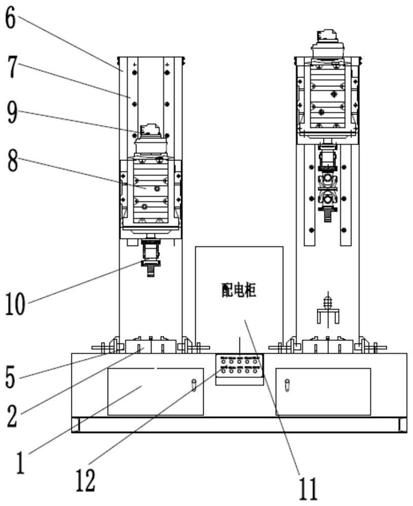
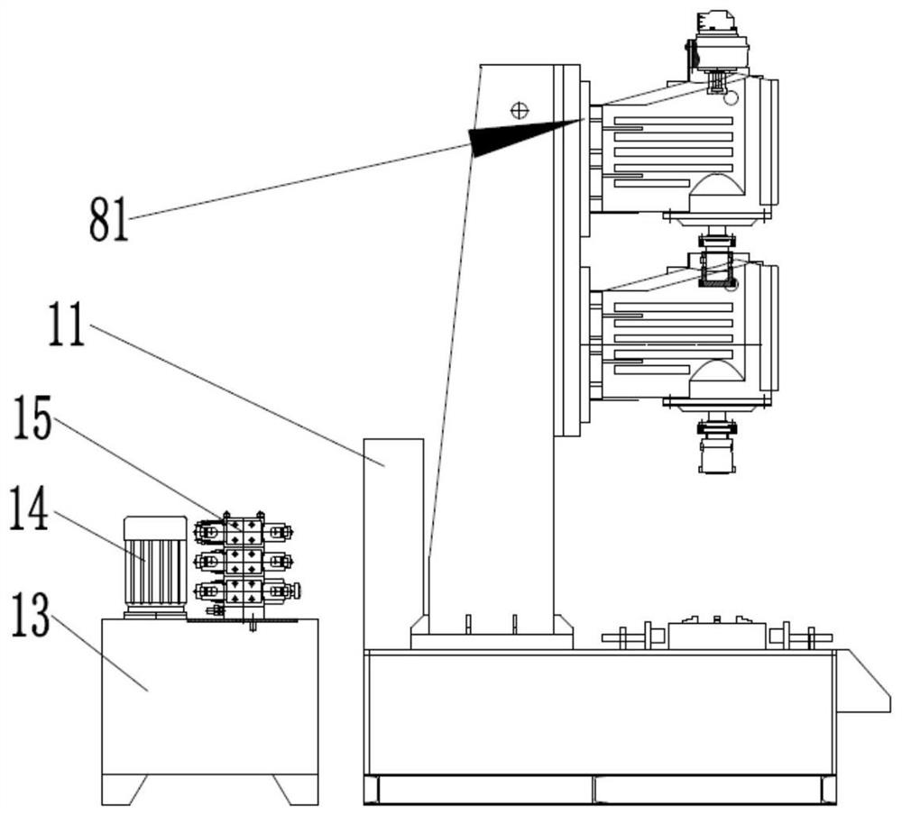
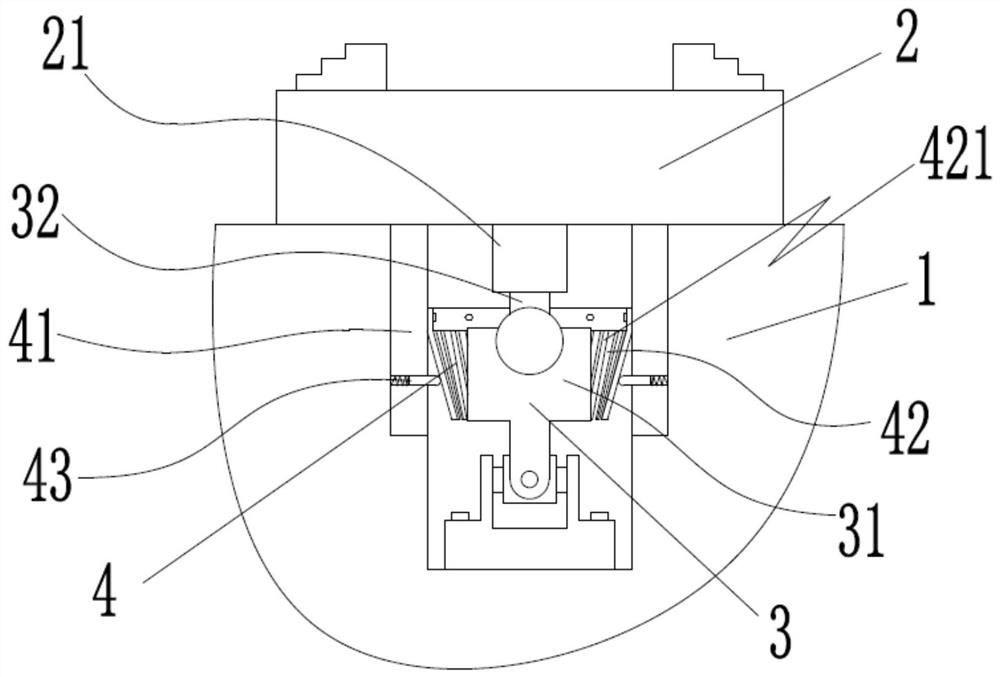
[0025] refer to Figure 1 to Figure 5 To further explain this application, such as figure 1 and figure 2 A plug valve sealing grinding machine shown includes a workbench 1, on which there is at least one column 6, and a back plate 87 of a gear box 8 is slidably matched with the slide rail 7 on the column 6, And an oil cylinder is connected between the gear box 8 and the column 6 so that the gear box 8 can be arranged on the column 6 in a liftable manner, an...


PUM


Abstract

The invention discloses a plug valve seal grinding machine, which comprises a workbench with at least one upright column, wherein it also includes a gear box arranged on the upright column in a liftable manner, a universal mechanism arranged in the workbench, and a The fixed clamping seat used to fix the valve seat on the workbench and the clamping mechanism set on the workbench and used to fix the fixed clamping seat, the input shaft of the gearbox is fixedly connected with a hydraulic motor, and a plug body passes through A telescoping mechanism is fixedly connected with the output shaft of the gearbox, wherein the universal mechanism includes a universal joint whose one end is fixedly connected to the bottom of the receiving hole on the workbench and a guide connected to the other end of the universal joint through a joint bearing. rod, and the guide rod is connected with the guide sleeve of the fixed clamp seat by sliding fit. The invention prevents the phenomenon of occlusal jamming in the working process, balances the force on the valve body and the plug body, and has high processing precision.

Description

technical field [0001] The invention relates to the technical field of valve body grinding, in particular to a plug valve sealing grinding machine. Background technique [0002] Due to the processing error between the cock valve body and the plug body, that is, the taper between the valve body and the plug body is not so good, and there is a gap between the surfaces, which will leak when pressurized. In order to overcome this defect, Usually, the plug body is coated with abrasive material, and then the plug body is put into the valve body to make the valve body and the plug body grind each other to achieve good fit and smoothness. However, it is necessary to ensure the plug body and the valve body during the grinding process. The body is on the same vertical plane in height so that the plug body can enter the valve body for grinding, and avoid the phenomenon of seizure during grinding. In the existing technology, some grinding equipment adjusts the position of the valve body...

Claims


Application Information

Patent Timeline
Patent Type & Authority Patents(China)
IPC IPC(8): B24B37/00B24B37/34
CPCB24B37/00B24B37/34
Inventor 李珍武李珍贤
Owner 浙江优机机械科技有限公司
Why Eureka
Try Eureka