Full-automatic detection reversing mechanism

A reversing mechanism and fully automatic technology, applied in the direction of measuring devices, measuring instrument components, instruments, etc., can solve problems such as sorting errors and low efficiency of manual sorting, and achieve the effect of reducing work intensity

Pending Publication Date: 2021-06-01
平湖市华晟精密机械股份有限公司
View PDF0 Cites 0 Cited by
  • Summary
  • Abstract
  • Description
  • Claims
  • Application Information

AI Technical Summary

Problems solved by technology

[0002] With the development of science and technology, the application range of product automation production technology is becoming more and more extensive; product packaging has neatness requirements, and it is necessary to ensure that the product direction is consistent. Usually, the direction of the product is adjusted through the manual sorting process before product packaging, but manual sorting The picking efficiency is low, and the problem of sorting errors is prone to occur under continuous work

Method used


Image

  • Full-automatic detection reversing mechanism
  • Full-automatic detection reversing mechanism
  • Full-automatic detection reversing mechanism

Examples


Embodiment 1

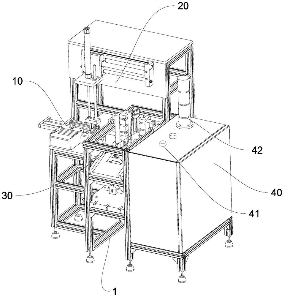
[0035] The frame 1 and the feeding mechanism 10, the transfer mechanism 20, the detection reversing mechanism 30 and the control mechanism 40 installed on the frame 1;

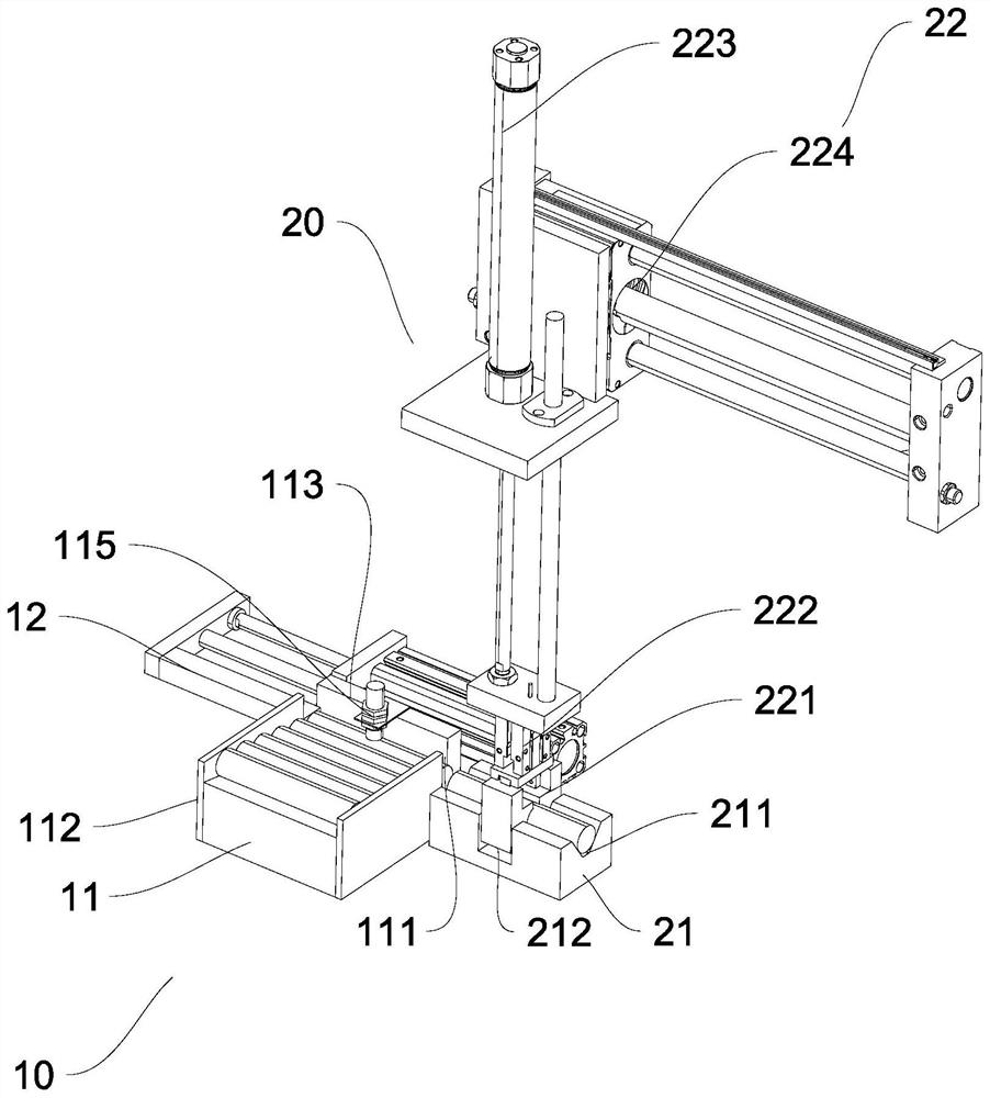
[0036] The feeding mechanism 10 includes a feeding platform 11 and a first pushing mechanism 12 installed on the feeding platform 11;

[0037] The transfer mechanism 20 includes a turntable 21, a grabbing mechanism 22, a limit mechanism 23 and a second push mechanism 24, the turntable 21 is fixed on one side of the feeding platform 11, and the grabbing mechanism 22 is arranged on the turntable 21 above, the limiting mechanism 23 is arranged on the right side of the grasping mechanism 22, and the second pushing mechanism 24 is arranged on the rear side of the limiting mechanism 23;

[0038] The detection reversing mechanism 30 includes a power source 31, a first push head 32, a second rotary push head 33, a temporary placement frame 34 and a discharge plate 35, and the temporary placement frame 34 is arranged o...

Embodiment 2

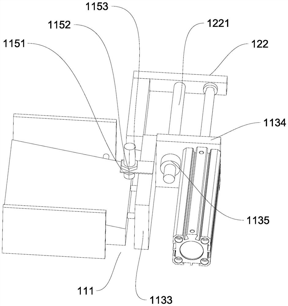
[0043] The upper end surface of the feed table 11 is an inclined surface, and guide holes 1121 are provided on both sides of the feed table 11, and a slide bar 1122 is arranged in the guide hole 1121, and one end of the slide bar 1122 is threadedly connected with a side plate 112 , the front end of the feeding table 11 is provided with a guide hole 1131, the guide hole 1131 is provided with a slide bar 1132, and one end of the slide bar 1132 is threaded with an L-shaped baffle 113, and the feed Table 11 is surrounded by side plate 112 and L-shaped baffle 113 to form discharge port 111; said first pushing mechanism 12 includes cylinder one 121 and L-shaped ejector rod 122, and said cylinder 121 is arranged on L-shaped baffle 113 , the L-shaped ejector rod 122 is connected to the piston rod 1211 of the cylinder one 121 , and one end of the L-shaped ejector rod 122 is located in the discharge port 111 .

[0044] Such as image 3 , Figure 4 and Figure 5 As shown, the feeding ...

Embodiment 3

[0046] The middle part of the top of the L-shaped baffle plate 113 is provided with a limit rod 115, and the limit rod 115 includes a fixed block 1151, a fastening bolt 1152 and a stud one 1153, and the fastening bolt 1152 is arranged on the upper end of the fixed block 1151 and the At the lower end, the first stud 1153 passes through the through hole in the middle of the fixing block 1151 and is connected with the fastening bolt 1152 .

[0047] Such as image 3 As shown, the lower end of the stud one 1153 is located at the upper end of the workpiece in the discharge port 111, and the stud one 1153 can ensure that there is always only one workpiece in the discharge port 111, preventing the workpiece from rolling over in the feed table 11. Quickly lead to the accumulation of workpieces in the discharge port 111, the threaded connection form of the stud 1153 and the fastening bolt 1152 can change the distance from the lower end of the stud 1153, and adjust the optimal distance f...


PUM


Abstract

The invention relates to the field of full-automatic equipment, in particular to a full-automatic detection reversing mechanism, which comprises a rack, a feeding mechanism, a transfer mechanism, a detection reversing mechanism and a control mechanism, and the feeding mechanism, the transfer mechanism, the detection reversing mechanism and the control mechanism are mounted on the rack; the feeding mechanism comprises a feeding table and a first pushing mechanism mounted on the feeding table; the transfer mechanism is arranged on one side of the feeding mechanism; the detection reversing mechanism comprises a power source, a first pushing head, a second rotating pushing head, a temporary placing frame and a discharging plate, the temporary placing frame is arranged on the left side of a limiting mechanism, a sensor is arranged in a groove of the temporary placing frame, and the discharging plate is arranged on the left side of the temporary placing frame, the first pushing head and the second rotating pushing head are arranged at the top of the power source; according to the full-automatic detection reversing mechanism, through linkage of the feeding mechanism, the transfer mechanism, the detection reversing mechanism and the control mechanism, the functions of automatic continuous detection and reversing of workpieces are achieved, and the working intensity of workers is reduced.

Description

technical field [0001] The invention relates to the field of fully automatic equipment, and relates to a fully automatic detection and reversing mechanism. Background technique [0002] With the development of science and technology, the application range of product automation production technology is becoming more and more extensive; product packaging has neatness requirements, and it is necessary to ensure that the product direction is consistent. Usually, the direction of the product is adjusted through the manual sorting process before product packaging, but manual sorting The picking efficiency is low, and sorting errors are prone to occur under continuous work. [0003] In order to solve the deficiencies in the prior art, it is necessary to design a fully automatic detection and reversing mechanism with a simple structure and high sorting efficiency. Contents of the invention [0004] In order to solve the problems of the prior art, the invention provides a fully au...

Claims


Application Information

Patent Timeline
Patent Type & Authority Applications(China)
IPC IPC(8): G01D21/00G01D11/00
CPCG01D11/00G01D21/00
Inventor 蒋明权
Owner 平湖市华晟精密机械股份有限公司
Why Eureka
Try Eureka