A multifunctional and safe charging pile for new energy vehicles

A new energy vehicle, safe technology, applied in the direction of electric vehicle charging technology, charging stations, electric vehicles, etc., can solve the problems of unusable charging piles, blocked charging, waste of resources, etc., to avoid waste of resources and space. Effects of Limiting and Ensuring Fair Use

Active Publication Date: 2021-11-09
NANTONG INST OF TECH
View PDF12 Cites 0 Cited by
  • Summary
  • Abstract
  • Description
  • Claims
  • Application Information

AI Technical Summary

Problems solved by technology

[0004] The purpose of the present invention is to provide a multifunctional and safe new energy vehicle charging pile to solve the problem that the general new energy vehicle charging piles proposed in the above background technology have various positions, and it is often difficult to approach the charging pile when the car is charging, thus making charging blocked. , which is not conducive to the use of consumers, resulting in a waste of resources, and the general charging pile completely depends on the power supply of the AC grid. When the grid fails or the power is cut off, the charging pile cannot be used, which hinders the development of new energy vehicles and affects consumption The normal life of consumers, while increasing the consumption of costs, is not conducive to the full profitability of charging piles, and has brought about product defects.

Method used


Image

  • A multifunctional and safe charging pile for new energy vehicles
  • A multifunctional and safe charging pile for new energy vehicles
  • A multifunctional and safe charging pile for new energy vehicles

Examples


Embodiment

[0036] refer to Figure 1-8 , the present invention will be described in further detail below in conjunction with accompanying drawing:

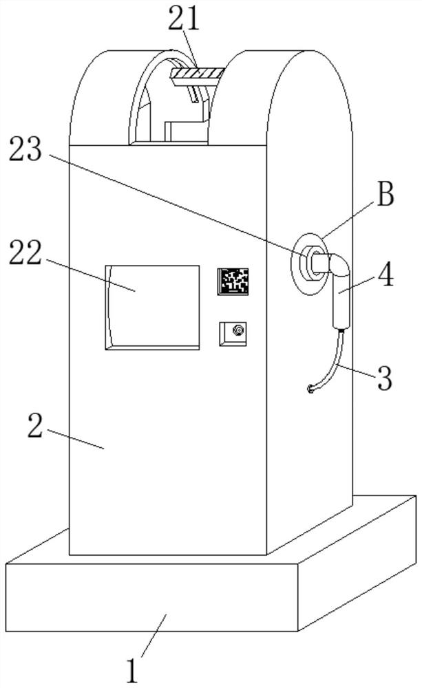
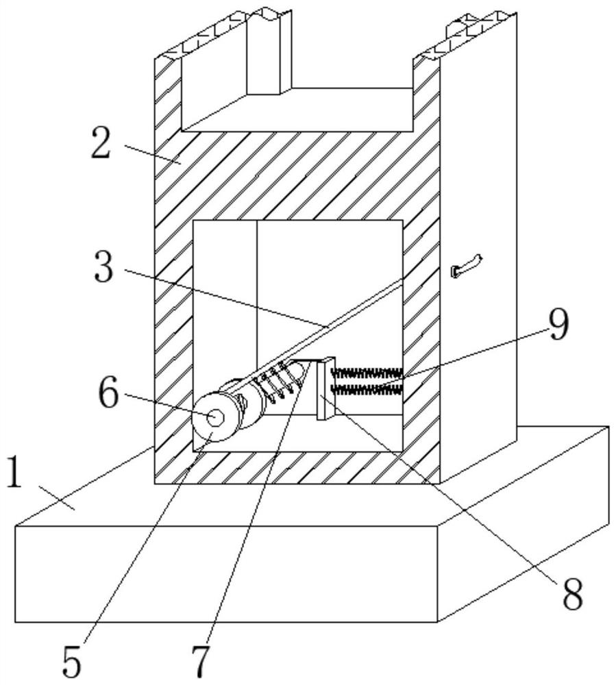
[0037] refer to figure 1 and figure 2 In this embodiment, a multifunctional and safe new energy vehicle charging pile is proposed, which includes a base 1, a main body 2 is fixedly connected to the top surface of the base 1, and a cavity 1 and a cavity 2 are respectively opened in the main body 2. , the top surface and the side wall of the cavity 2 are respectively provided with a chute and a through hole, and the bottom side wall of the main body 2 is slidably sleeved with a lead 3, and a plug 4 is installed at one end of the lead 3, and the lead 3 The other end of the wire extends into the groove one, and the extending end of the wire one 3 is fixedly wound with a roller 5, the roller 5 is fixedly sleeved with a rotating shaft 6, and the other end of the rotating shaft 6 is rotationally connected with the side wall of the cavity one, And...


PUM


Abstract

The invention discloses a multifunctional and safe charging pile for new energy vehicles, which includes a base, a main body is fixedly connected to the top surface of the base, and a cavity 1 and a cavity 2 are respectively opened in the main body. A chute and a through hole are provided on the top surface and the side wall of the cavity two respectively, and a lead wire 1 is slidably sleeved on the side wall of the bottom end of the main body, and a plug is installed at one end of the lead wire 1, and a plug is installed at the other end of the lead wire 1. Extending into groove 1, and the extending end of wire 1 is fixedly wound with a roller, and the rotating shaft is fixedly sleeved inside the roller. The invention makes the new energy vehicle not need to be close to the charging pile, avoids the limitation of the site, and makes the charging smooth , which is conducive to the use of consumers, avoids the waste of vacant resources, and can reduce the transmission power of the AC grid, thereby saving cost consumption and increasing operating profits. At the same time, it is not easily affected by AC grid damage or power outages, which is convenient for consumers use.

Description

technical field [0001] The invention relates to the field of new energy vehicles, in particular to a multifunctional and safe charging pile for new energy vehicles. Background technique [0002] Car charging is an important part of the development of new energy vehicles. The lack of charging system infrastructure will seriously restrict the development of the electric vehicle industry. The function of charging piles is similar to that of fuel dispensers in gas stations. Various types of new energy vehicles are charged. The input end of the charging pile is directly connected to the AC power grid, and the output end is equipped with a charging plug for charging new energy vehicles. [0003] The general new energy vehicle charging piles on the market have various locations, and it is often difficult to get close to the charging piles when the car is charging, which hinders the charging, is not conducive to the use of consumers, and brings waste of resources, and the general ch...

Claims


Application Information

Patent Timeline
Patent Type & Authority Patents(China)
IPC IPC(8): B60L53/31B60L53/16B60L53/18B60L53/51H02J7/35
CPCB60L53/16B60L53/18B60L53/31B60L53/51H02J7/35Y02T10/70Y02T10/7072Y02T90/12Y02T90/14
Inventor 冒兴峰罗鹰陆兆钠宗婉愉
Owner NANTONG INST OF TECH
Why Eureka
Try Eureka