
Melt-blown cloth processing device

A processing device and technology of melt-blown cloth, applied in the direction of non-woven fabrics, mechanical cleaning, textiles and papermaking, etc., can solve the problems of melt-blown cloth pulling distortion, poor quality, and reducing the quality of melt-blown cloth production and processing, etc., to achieve The effect of improving production quality and improving suction efficiency

Active Publication Date: 2021-06-04
苏州市佳和无纺制品有限公司
View PDF8 Cites 0 Cited by
  • Summary
  • Abstract
  • Description
  • Claims
  • Application Information

AI Technical Summary

Problems solved by technology

[0002] When the melt-blown cloth passes through the adjacent side of the miscellaneous air duct during the conveying process, the miscellaneous air duct can only absorb the adhered fibers on the surface of the melt-blown cloth once, and it is difficult to use the miscellaneous air duct to remove the melt-blown cloth. The surface-adhesive fibers are continuously reciprocated for multiple suctions, resulting in low suction efficiency and poor quality of the surface-adhesive fibers of the melt-blown cloth, and the melt-blown cloth during the transmission process will not be compacted on both sides of the melt-blown cloth. Fixed, because the texture of the melt-blown cloth is relatively light and thin, the melt-blown cloth will be adsorbed and attached to the suction inlet of the miscellaneous air duct due to the suction of the miscellaneous air duct, resulting in the adsorption of the melt-blown cloth on the miscellaneous air duct Under the influence of pulling and twisting, it is difficult to ensure the orderly transmission and processing of the melt blown cloth, and the quality of the production and processing of the melt blown cloth is reduced, and it is difficult to meet the needs of production and use.

Method used


Image

  • Melt-blown cloth processing device
  • Melt-blown cloth processing device
  • Melt-blown cloth processing device

Examples


Embodiment

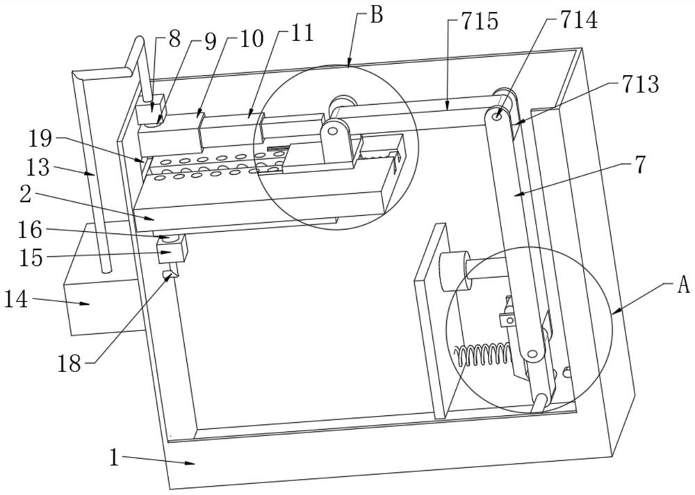
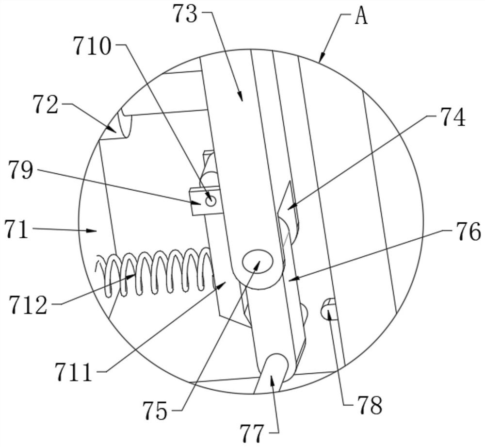
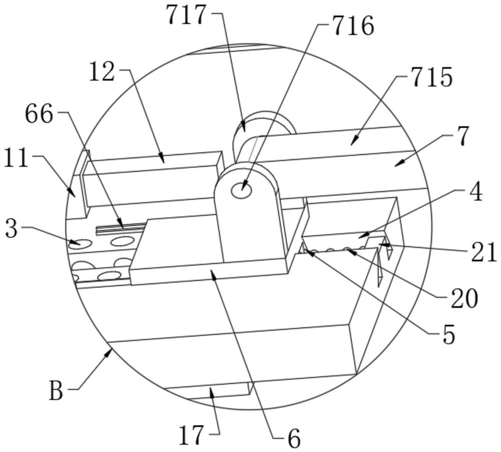
[0034] see Figure 1-6 , a processing device for melt-blown cloth, which consists of a dust cover 1, a pressing assembly 6, a conveying assembly 7, a first suction fan 8 and a second suction fan 15.

[0035]Wherein, the dust cover 1 can prevent dust from entering the components such as the pressing assembly 6 and the conveying assembly 7. The inner wall of the dust cover 1 is welded with a first support plate 2, and the upper surface of the first support plate 2 is provided with a first slide. Groove 4, the first slider 5 is slidably connected on the inner wall of the first chute 4, through the mutual cooperation between the first chute 4 and the first slider 5, the first slider 5 can be moved along the first slide Trajectory movement of slot 4.

[0036] Among them, due to the relatively light texture of the melt-blown cloth, the melt-blown cloth will be adsorbed and attached to the suction inlet of the miscellaneous air duct due to the suction of the miscellaneous air duct, ...


PUM


Abstract

The invention discloses a melt-blown cloth processing device which is composed of a dust cover, a pressing assembly, a conveying assembly, a first suction fan and a second suction fan. Melt-blown cloth is placed on the upper surfaces of a pair of L-shaped plates, and a first air cylinder is started to drive a connecting plate to move in a horizontal direction; through mutual cooperation of a second sliding groove and a pair of pressing plates, the connecting plate moves to drive the pair of pressing plates to move along the track of the second sliding groove; through mutual cooperation between the pair of pressing plates and the pair of L-shaped plates, edges of the melt-blown cloth can be pressed, the melt-blown cloth is prevented from being pulled, twisted and deformed under the adsorption effect of an impurity suction air pipe, so that the production quality is improved; through mutual cooperation of the conveying assembly, the first suction fan and the second suction fan, fibers adhered to the surface of the melt-blown cloth can be continuously and repeatedly sucked and removed for multiple times, the sucked and removed fibers enter a waste box from a first air outlet pipe and a second air outlet pipe to be collected, and thus the suction and removal efficiency is improved.

Description

technical field [0001] The invention relates to the technical field of melt-blown cloth, and more specifically, relates to a processing device for melt-blown cloth. Background technique [0002] When the melt-blown cloth passes through the adjacent side of the miscellaneous air duct during the conveying process, the miscellaneous air duct can only absorb the adhered fibers on the surface of the melt-blown cloth once, and it is difficult to use the miscellaneous air duct to remove the melt-blown cloth. The surface-adhesive fibers are continuously reciprocated for multiple suctions, resulting in low suction efficiency and poor quality of the surface-adhesive fibers of the melt-blown cloth, and the melt-blown cloth during the transmission process will not be compacted on both sides of the melt-blown cloth. Fixed, because the texture of the melt-blown cloth is relatively light and thin, the melt-blown cloth will be adsorbed and attached to the suction inlet of the miscellaneous ...

Claims


Application Information

Patent Timeline
Patent Type & Authority Applications(China)
IPC IPC(8): D04H1/54D06G1/00
CPCD04H1/54D06G1/00
Inventor 谢亚洲
Owner 苏州市佳和无纺制品有限公司
Learn More