Polyurethane thermal insulation composite tube and forming device thereof

A thermal insulation compounding and forming device technology, applied in the direction of thermal insulation, pipes and tubes through thermal insulation protection, can solve the problems of weakened bonding force, reduced thermal insulation effect, low processing efficiency, etc., to achieve detachment prevention, high integrity, adhesive uniform and stable effect

Active Publication Date: 2021-10-19
浙江天诚绝热科技股份有限公司
View PDF8 Cites 1 Cited by
  • Summary
  • Abstract
  • Description
  • Claims
  • Application Information

AI Technical Summary

Problems solved by technology

[0005] (1) Although the processing of the inner tube, polyurethane layer and outer tube is a continuous production line, it is formed through three stages of processing, and each stage is processed to be relatively stable before combined processing. Not only the processing efficiency is low, but it will also cause The integrity of the pipe is reduced
[0006] (2) The plastic pipe is covered with polyurethane insulation layer after spray cooling and blast drying. At this time, since the plastic pipe has been formed stably, this will weaken the bonding force between the polyurethane insulation layer and the plastic pipe, resulting in During the later use, the polyurethane insulation layer and the plastic pipe become loose and detached, reducing the insulation effect
[0007] (3) When the polyurethane foam layer is formed, it is injected from the side of the outer wall of the inner tube through the high-pressure mixing gun head, and the polyurethane foam material is pushed and squeezed to cover the outer circumference of the inner tube, but the polyurethane foam material is discharged after injection. Will solidify quickly, which will lead to uneven distribution of polyurethane foam material, resulting in unstable insulation effect
[0008] (4) The outer tube of the polyurethane thermal insulation composite tube has a certain degree of flexibility when it is not completely fixed at the initial stage of forming, and there is a risk of distortion and deformation if it is directly pulled

Method used


Image

  • Polyurethane thermal insulation composite tube and forming device thereof
  • Polyurethane thermal insulation composite tube and forming device thereof
  • Polyurethane thermal insulation composite tube and forming device thereof

Examples


Embodiment 1

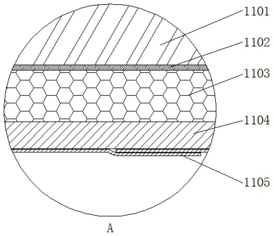
[0059] Such as figure 1 , figure 2 , Figure 14 and Figure 15 As shown, the polyurethane thermal insulation composite pipe includes an inner pipe 1101. The inner pipe 1101 can be a steel pipe as a supporting frame. An outer tube 1104 is provided on the outer jacket, and a polyurethane insulation layer 1103 is filled between the outer tube 1104 and the anticorrosion layer 1102 on the inner tube 1101, and the outer tube 1104 is covered with a heat insulating layer 1105, which can be made of aluminum foil.

[0060] By setting the anti-corrosion layer 1102 between the inner pipe 1101 and the polyurethane insulation layer 1103, it is possible to prevent the outer wall of the inner pipe 1101 from being rusted and rotted, resulting in loosening and separation from the polyurethane insulation layer 1103, and the heat insulation layer 1105 can not only improve the composite pipe as a whole. Insulation performance, and can protect the outer pipe 1104 directly from external collisio...

Embodiment 2

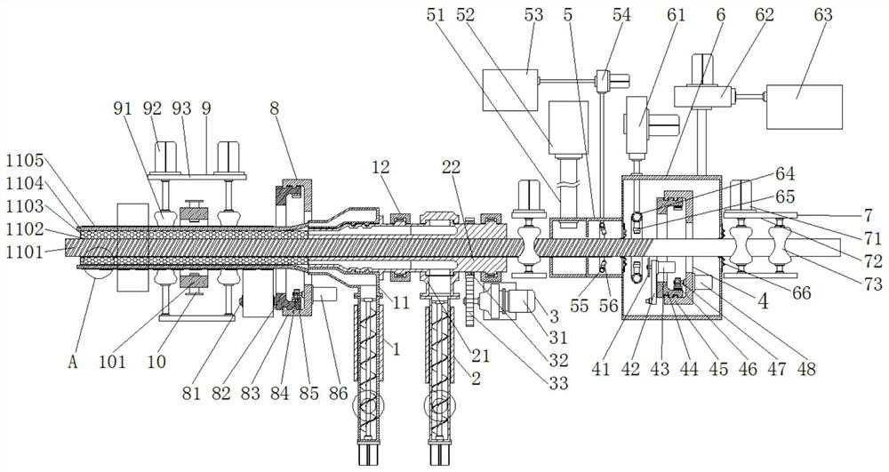
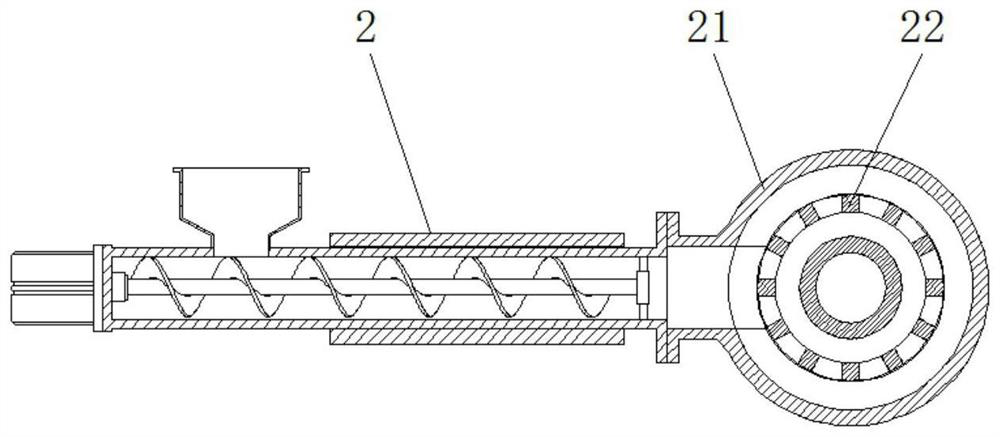
[0065] Such as figure 1 , Figure 3-Figure 13 As shown, this embodiment discloses a molding device for a polyurethane thermal insulation composite pipe based on Embodiment 1, including a foaming extruder head 22, and the middle of the foaming extruder head 22 is provided with a diameter matching inner pipe 1101 A round hole, and the outer rotation sleeve of the foaming extruder head 22 is provided with an outer tube extruder head 11, and the tail end side of the foaming extruder head 22 is provided with a spray box 5, and the spray box 5 is far away from the foaming extruder. One side of the head 22 is provided with a notch mechanism 4, the notch mechanism 4 includes a first swivel 44, one side of the first swivel 44 is connected with a cutter head 41 through a support arm 42, the foam extrusion head 22 A winding mechanism 8 is provided on one side of the head end, and the winding mechanism 8 includes a second swivel 82 , and a drum 81 is arranged on one side of the second sw...


PUM


Abstract

The invention relates to the technical field of polyurethane thermal insulation materials, in particular to a polyurethane thermal insulation composite tube. The polyurethane thermal insulation composite tube comprises an inner tube, wherein the outer wall of the inner tube is evenly covered with an anti-corrosion layer; the inner tube is sleeved with an outer tube; a polyurethane insulation coating is filled between the anti-corrosion layer on the outer tube and the anti-corrosion layer on the inner tube; the outer tube is wrapped with a thermal insulation layer. A forming device of the polyurethane thermal insulation composite tube comprises a foaming extrusion machine head, wherein a round hole matched with the diameter of an inner tube is formed in the middle of the foaming extrusion machine head, the foaming extrusion machine head is rotationally sleeved with an outer tube extrusion machine head, and a spraying box is arranged at one side of the tail end of the foaming extrusion machine head. By means of the matching structure of the foaming extrusion machine head and the outer tube extrusion machine head, the inner tube can penetrate through, meanwhile, wrapping and covering of the outer tube and filling of the polyurethane insulation coating are conducted, the inner tube, the polyurethane insulation coating and the outer tube are synchronously formed in a section of area, higher efficiency is achieved, and the integrity of the tube is higher after the tube is formed.

Description

technical field [0001] The invention relates to the technical field of polyurethane thermal insulation materials, in particular to a polyurethane thermal insulation composite pipe and a forming device thereof. Background technique [0002] Polyurethane insulation pipe is made of high-functional polyether polyol composite material and polymethyl polyphenyl polyisocyanate as raw materials through chemical reaction foaming. Polyurethane insulation pipes are used in various indoor and outdoor pipelines, central heating pipelines, central air-conditioning pipelines, chemical, pharmaceutical and other industrial pipelines for heat preservation and cold preservation projects. Overview Since the birth of polyurethane synthetic materials in the 1930s, polyurethane foam insulation pipes have been rapidly developed as an excellent thermal insulation material, and its application range is becoming wider and wider. It is widely used in various pipelines such as heating, cooling, oil tra...

Claims


Application Information

Patent Timeline
Patent Type & Authority Applications(China)
IPC IPC(8): F16L9/00F16L59/02B29C48/21B29C48/151B29C48/00B29L23/00
CPCF16L9/00F16L59/02F16L59/028B29C48/21B29C48/151B29C48/001B29L2023/00
Inventor 倪永明
Owner 浙江天诚绝热科技股份有限公司
Why Eureka
Try Eureka