
A monitoring system and monitoring method for chain-type drive mud scraper

A technology of monitoring system and mud scraper, applied in separation methods, chemical instruments and methods, sedimentation separation, etc., can solve the problems of easily damaged mud rake body, slow rotation of suspension shaft, waste of manpower and material resources, etc., and achieve the accuracy of automatic monitoring high effect

Active Publication Date: 2022-04-26
NINGBO BAOXIN STAINLESS STEEL
View PDF7 Cites 0 Cited by
  • Summary
  • Abstract
  • Description
  • Claims
  • Application Information

AI Technical Summary

Problems solved by technology

[0003] However, the following two types of problems are prone to occur in this type of equipment driven by chains at present: 1. When the chain falls off or breaks, the drive motor will continue to rotate, and the actually driven mud rake has stopped working. In the HMI screen It still shows that the mud rake drive motor is running normally. In the current industrial automation factory, the automatic efficiency is high. The operator can directly operate and monitor the field equipment through the HMI in the operating room.
Generally, the operator will go to the site to confirm the site conditions of the equipment only when the equipment reports a failure in the HMI; 2. The suspension shaft rotates too slowly due to too many sludge deposits deposited at the bottom of the tank
For such low-speed and low-speed equipment on site, it is often difficult to find the abnormal rotation of the suspension shaft in time during daily inspections. The rotation speed of the mud rake is very slow. Generally, it takes 6 to 10 minutes to make a circle. The torque of the high-speed rotating equipment is very large. Once it stops, the mud at the bottom will sink and agglomerate. After a long time, the mud will stop and it will be difficult to open the mud rake again. If the torque is too high, it will easily damage the mud rake body. It can only clear the pond and mud, which will increase the downtime, and the workload will be very large, which will waste a lot of manpower and material resources

Method used


Image

  • A monitoring system and monitoring method for chain-type drive mud scraper
  • A monitoring system and monitoring method for chain-type drive mud scraper

Examples


Embodiment Construction

[0024] The present invention will be further described in detail below in conjunction with the accompanying drawings and embodiments.

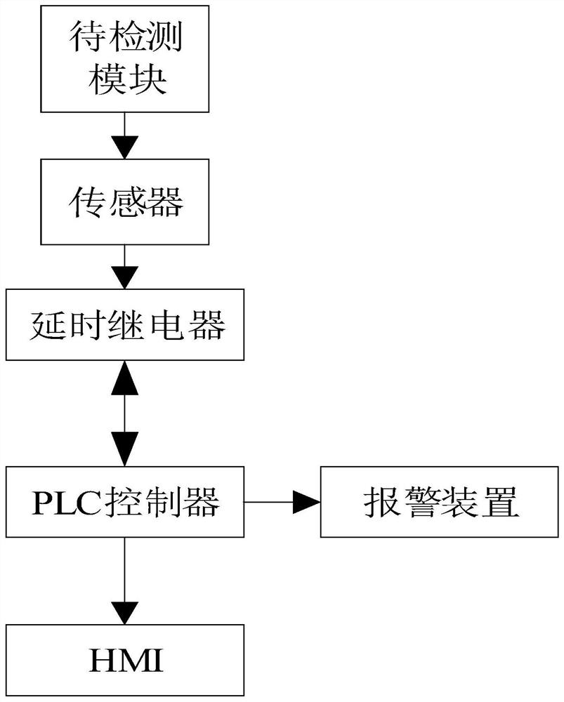
[0025] The chain drive mud scraper adopts the existing central suspension drive chain drive mud scraper, wherein the chain drive mud scraper includes: working bridge, suspension shaft installed in the center of the working bridge, driving device installed on the working bridge And the transmission device, the driving device includes a driving motor, the transmission device includes a driving gear and a driven gear, the driving gear is sleeved on the motor shaft of the driving motor, and the driving gear and the driven gear are connected by a transmission chain. In addition, the driven gear The gear is meshed with the suspension shaft, and the driving motor drives the driving gear to work, and the driving gear drives the driven gear to rotate through the transmission chain, so that the driven gear also drives the suspension shaft to rotate accor...


PUM


Abstract

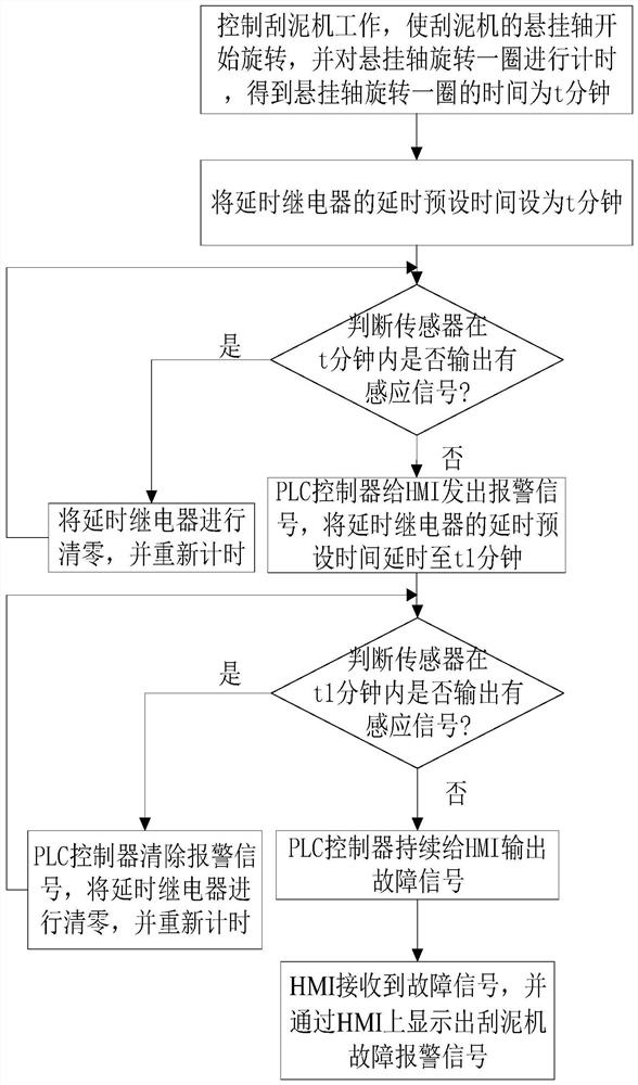
The invention relates to a monitoring system for a chain-type transmission mud scraper, characterized in that: the monitoring system includes: a module to be detected, located on the outer surface of the suspension shaft; a sensor for sensing the module to be detected, the suspension The shaft can rotate relative to the sensor, and the sensor outputs an induction signal when it senses the module to be detected; the delay relay, the control circuit of the delay relay is connected to the signal output end of the sensor; the PLC controller, the PLC controller and the delay relay connected with each other; HMI, the HMI is connected with the PLC controller for communication. Also disclosed is a monitoring method using the above-mentioned monitoring system for a chain drive mud scraper. The automatic monitoring accuracy of the monitoring system is high and the abnormal rotation of the suspension shaft can be found in time.

Description

technical field [0001] The invention relates to the technical field of sewage treatment, in particular to a monitoring system and a monitoring method for a chain-type transmission mud scraper. Background technique [0002] The wastewater treatment station needs to use a sludge clarifier to separate sludge and wastewater during the wastewater treatment process. The most important equipment in sludge clarification is the sludge scraper, also known as mud rake, which is used to prevent sludge sedimentation and help sludge transportation. In modern times, the most widely used in the sewage treatment industry is also the central suspension drive chain drive type mud scraper. The conventional structure of this type of mud scraper is the driving device installed on the working bridge. The gear is driven by the motor, the running speed of the mud rake is changed through the gear ratio, and the torque of the mud rake is increased. The chain drive drives the worm gear, and the worm g...

Claims


Application Information

Patent Timeline
Patent Type & Authority Patents(China)
IPC IPC(8): B01D21/30B01D21/04
CPCB01D21/30B01D21/04
Inventor 王存军王小龙江琦雄梅杰柳雨汪富林
Owner NINGBO BAOXIN STAINLESS STEEL
Learn More