Device and method for automatic deoxygenation and moisture removal in transition chamber of vacuum glove box

A vacuum glove box, transition cabin technology, used in manipulators, climate sustainability, final product manufacturing, etc., can solve problems such as rising oxygen and moisture content, shortening the use time of the main box, etc.

Active Publication Date: 2022-07-12
FUQING BRANCH OF FUJIAN NORMAL UNIV +1
View PDF0 Cites 0 Cited by
  • Summary
  • Abstract
  • Description
  • Claims
  • Application Information

AI Technical Summary

Problems solved by technology

But sometimes, because the user is not familiar with the operation process or has not completed the operation according to the prescribed process, he hurriedly transfers the tools or materials into the main box. Because the moisture and oxygen are not completely removed, the oxygen and moisture in the main box The increase of the content will not only easily affect the effect of follow-up work, but also shorten the use time of the main box, and the main box must be frequently regenerated and restored after not being used for a long time

Method used


Image

  • Device and method for automatic deoxygenation and moisture removal in transition chamber of vacuum glove box

Examples


Embodiment 1

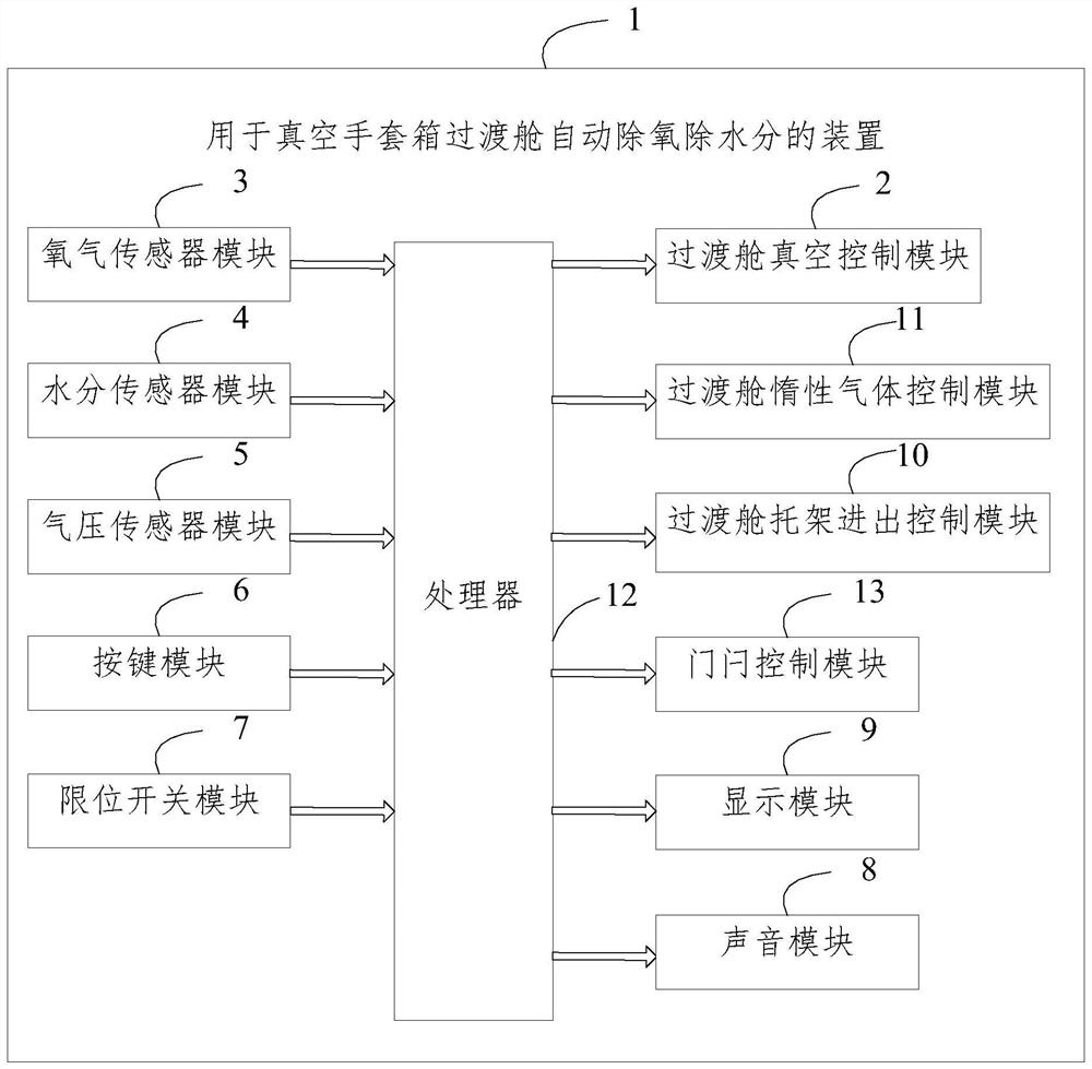
[0024] Please refer to figure 1 , a device 1 for automatic deoxygenation and moisture removal in a transition cabin of a vacuum glove box, including an oxygen sensor module 3, a moisture sensor module 4, an air pressure sensor module 5, a transition cabin vacuum control module 2, a transition cabin inert gas control module 11, a transition cabin the carriage access control module 10 and the processor 12;

[0025] The oxygen sensor module 3, the moisture sensor module 4, the air pressure sensor module 5, the transition cabin inert gas control module 11, the transition cabin vacuum control module 2 and the transition cabin bracket access control module 10 are respectively electrically connected to the processor 12;

[0026] The oxygen sensor module 3, the moisture sensor module 4 and the air pressure sensor module 5 respectively collect the data in the transition cabin and send them to the processor 12;

[0027] The processor 12 processes the received data and sends correspondi...

Embodiment 2

[0041] A method for automatic deoxygenation and moisture removal in a transition chamber of a vacuum glove box, comprising the steps of:

[0042] The oxygen sensor module, the moisture sensor module and the air pressure sensor module respectively collect the data in the transition cabin and send them to the processor;

[0043] The processor processes the received data and sends corresponding instructions to control the working states of the transition cabin inert gas control module and the transition cabin vacuum control module.

[0044] The described processor processes the received data and sends corresponding instructions to control the working states of the transition cabin inert gas control module and the transition cabin vacuum control module as follows:

[0045] The processor judges whether the data is greater than a preset value according to the received data, and if so, sends an instruction to the transition cabin vacuum control module, so that the transition cabin va...


PUM


Abstract

The device and method for automatic deoxygenation and moisture removal in the transition chamber of the vacuum glove box provided by the present invention are provided by setting an oxygen sensor module, a moisture sensor module, an air pressure sensor module, a transition chamber vacuum control module, a transition chamber inert gas control module, and a transition chamber. A carriage access control module and a processor; the oxygen sensor module, moisture sensor module, air pressure sensor module, transition cabin inert gas control module, transition cabin vacuum control module and transition cabin carriage access control module are respectively electrically connected to the processor. connection; the oxygen sensor module, the moisture sensor module and the air pressure sensor module respectively collect the data in the transition cabin and send them to the processor; the processor processes the received data and sends corresponding instructions Controlling the working state of the transition cabin inert gas control module and the transition cabin vacuum control module not only realizes the automatic removal of moisture and oxygen in the transition cabin, but also realizes the automatic entry and exit of the transition cabin tray.

Description

technical field [0001] The invention relates to the field of vacuum equipment, in particular to a device for automatic deoxygenation and moisture removal in a transition chamber of a vacuum glove box. Background technique [0002] The vacuum glove box is a laboratory equipment that fills the box with high-purity inert gas and circulates and filters out the active substances in it. The glove box is mainly composed of box body, transition cabin, gas purification, automatic control, etc. 2 , H 2 Clearance of O etc. Widely used in moisture-free, oxygen-free and dust-free environments, such as: lithium-ion batteries and materials, semiconductors, super capacitors, etc. in the research and development and production. [0003] The transition cabin is used as the transition space between the main box and the outside of the box. In order to avoid introducing moisture and oxygen into the main box, tools and materials need to be put into the transition cabin first, and then moved to...

Claims


Application Information

Patent Timeline
Patent Type & Authority Patents(China)
IPC IPC(8): B25J21/02
CPCB25J21/02Y02P70/50
Inventor 张荣刚范镜敏董全峰郑明森崔学阳孙宗强陈国明王炎红
Owner FUQING BRANCH OF FUJIAN NORMAL UNIV
Why Eureka
Try Eureka