Inlet and outlet moving mechanism of core cutter of spring machine

A technology of moving mechanism and movement knife, which is applied in the direction of manufacturing springs, other household appliances, household appliances, etc. from wires, which can solve the problems of all-in, all-out, and cannot meet the advanced technological requirements of secondary bending forming springs.

Inactive Publication Date: 2012-06-13
SHAOXING JIADU SPRING MACHINE
View PDF4 Cites 0 Cited by
  • Summary
  • Abstract
  • Description
  • Claims
  • Application Information

AI Technical Summary

Problems solved by technology

In the prior art, there is a core knife that uses a solenoid valve to control the lateral movement. Its defect is that the core knife can only move with a fixed stroke, either full in or full out; it cannot control the stroke and speed, and cannot adapt to the secondary bending forming spring. advanced process requirements

Method used


Image

  • Inlet and outlet moving mechanism of core cutter of spring machine
  • Inlet and outlet moving mechanism of core cutter of spring machine
  • Inlet and outlet moving mechanism of core cutter of spring machine

Examples


Embodiment

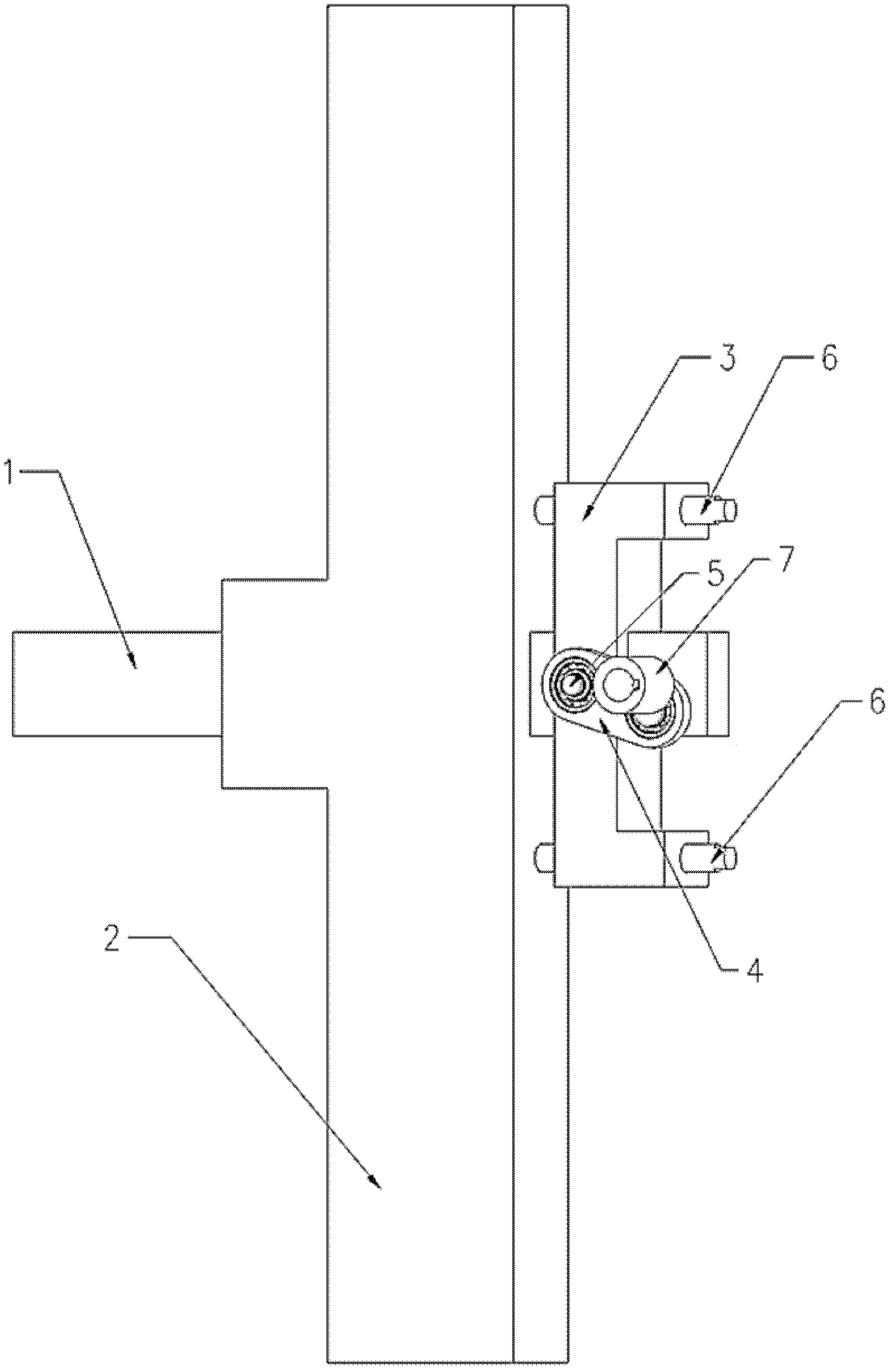
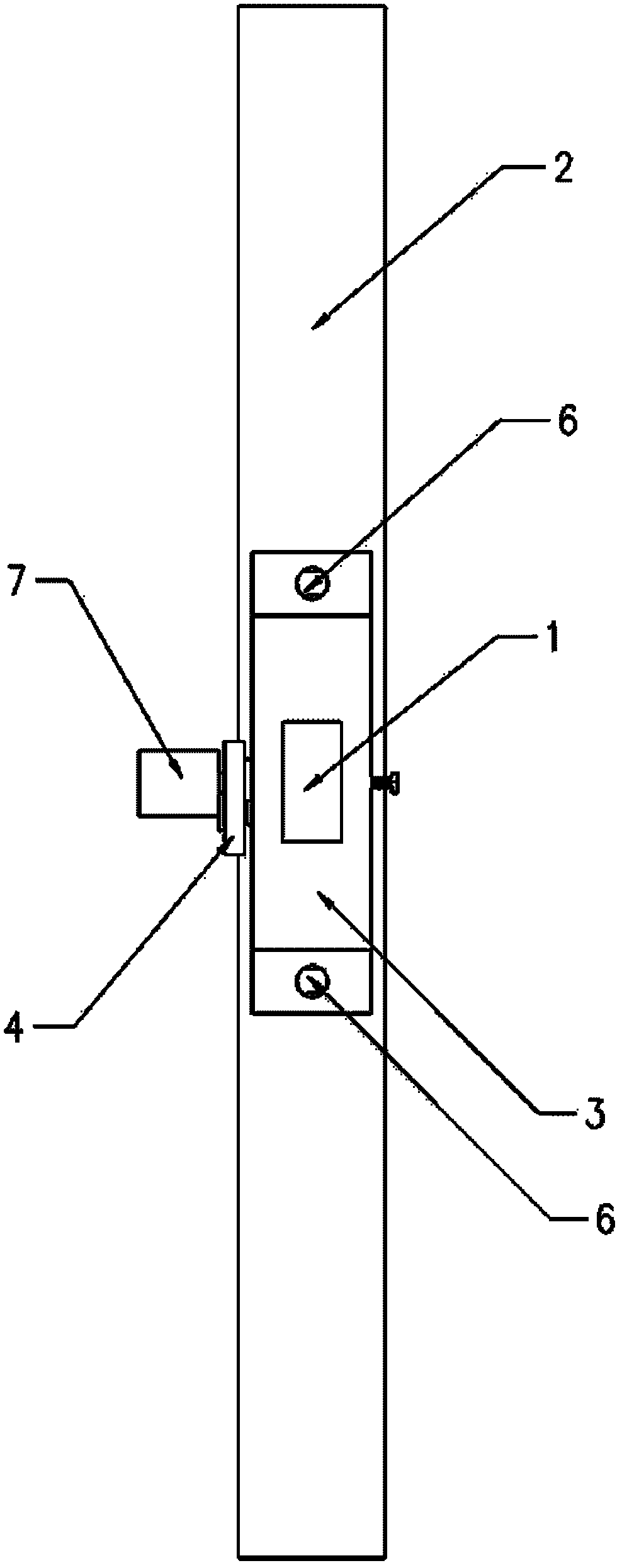
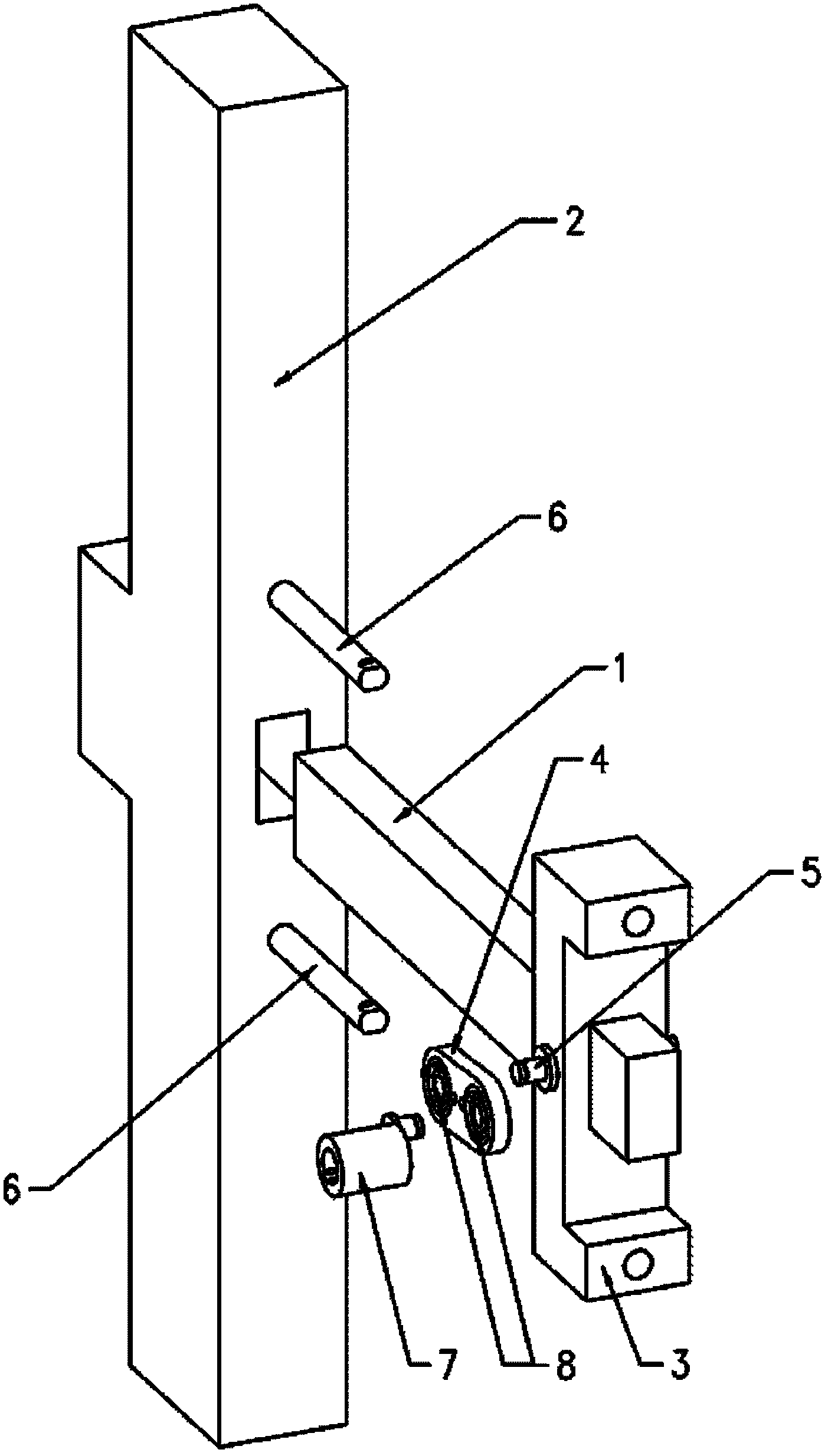
[0017] The in and out movement mechanism of the spring movement knife is as follows: Figure 1-Figure 3 As shown, there is a rectangular through hole protruding in the middle of the core knife seat 2 for installing the core knife 1. The core knife 1 is installed in the through hole of the core knife seat 2 and can slide back and forth. The rear end of the core knife 1 is fixed on the U-shaped seat with bolts. 3 up;

[0018] Two guide rods 6 are fixed on the back corresponding to the protrusion in the middle of the core knife seat 2, and the two through holes on the upper and lower sides of the U-shaped fixing seat 3 are sleeved on the guide rods; they can be hung on the guide rods and slide; Wearing bearing pin 5, outer covering bearing 8;

[0019] The two holes of the connecting rod 4 use bearings 8, one bearing 8 is sleeved on the pin shaft 5, and the other bearing 8 is sleeved on the eccentric protrusion of the eccentric sleeve 7, and the protrusions of the pin shaft 5 and...


PUM


Abstract

The invention relates to an inlet and outlet moving mechanism of a core cutter of a spring machine. The inlet and outlet moving mechanism comprises the core cutter, a core cutter seat, a U-shaped fixing seat, a connecting rod, a pin shaft, guide rods, an eccentric sleeve and bearings; a rectangular through hole is bulged at the middle of the core cutter seat for mounting the core cutter, and the rear end of the core cutter is fixed on the U-shaped seat through a bolt; the two guide rods are fixed on the back of the core cutter seat, an upper through hole and a lower through hole of the U-shaped fixing seat are sheathed on the guide rods; the U-shaped fixing seat can be hung on the guide rods for sliding; the pin shaft is fixedly arranged on the U-shaped fixing seat; and the two bearings are mounted in two holes of the connecting rod in parallel, one bearing is sheathed on the pin shaft, and the other bearing is sheathed on an eccentric bulge of the eccentric sleeve. When the eccentric sleeve receives torque from a motor for rotation, the connecting rod is driven to drive the U-shaped fixing seat to move horizontally, and the core cutter which is fixed on the U-shaped fixing seat can get in and out of the core cutter seat accordingly. The stepping motor is used for controlling the rotation angle and the rotation speed of the eccentric sleeve in the inlet and outlet moving mechanism disclosed by the invention, and the core cutter can get in and out of the core cutter seat according to process requirements, so that the inlet and outlet moving mechanism is particularly suitable for manufacturing saddle-shaped variable-diameter special-shaped springs.

Description

technical field [0001] The invention relates to the field of metal wire forming machinery, in particular to a mechanism for moving in and out of a spring core knife. Background technique [0002] The core knife is a necessary key component of the spring winding machine. During the coiling process of the spring, the steel wire is forced to be sent out and moves in one direction. There must be a push rod or a roller of the variable diameter mechanism to push the steel wire at three positions and from different directions, so as to change the forward direction of the steel wire and make it crimping to make the steel wire coiled into a spring. The core knife is equivalent to the fourth special ejector pin located in the center of the spring. In addition to controlling the diameter of the spring, after the spring is coiled, the core knife must cooperate with the cutter to cut off the steel wire, so that the finished spring can be separated from the raw steel wire. When winding...

Claims


Application Information

Patent Timeline
Patent Type & Authority Applications(China)
IPC IPC(8): B21F35/00B21F11/00
Inventor 俞度俞家林黄花丽
Owner SHAOXING JIADU SPRING MACHINE
Why Eureka
Try Eureka