Auxiliary tool for architectural design
An auxiliary tool and architectural design technology, applied in the direction of signs, instruments, display devices, etc., can solve the problems of inconvenient comparison and selection for designers, and achieve the effect of easy connection and disassembly
- Summary
- Abstract
- Description
- Claims
- Application Information
AI Technical Summary
Problems solved by technology
Method used
Image
Examples
Embodiment 1
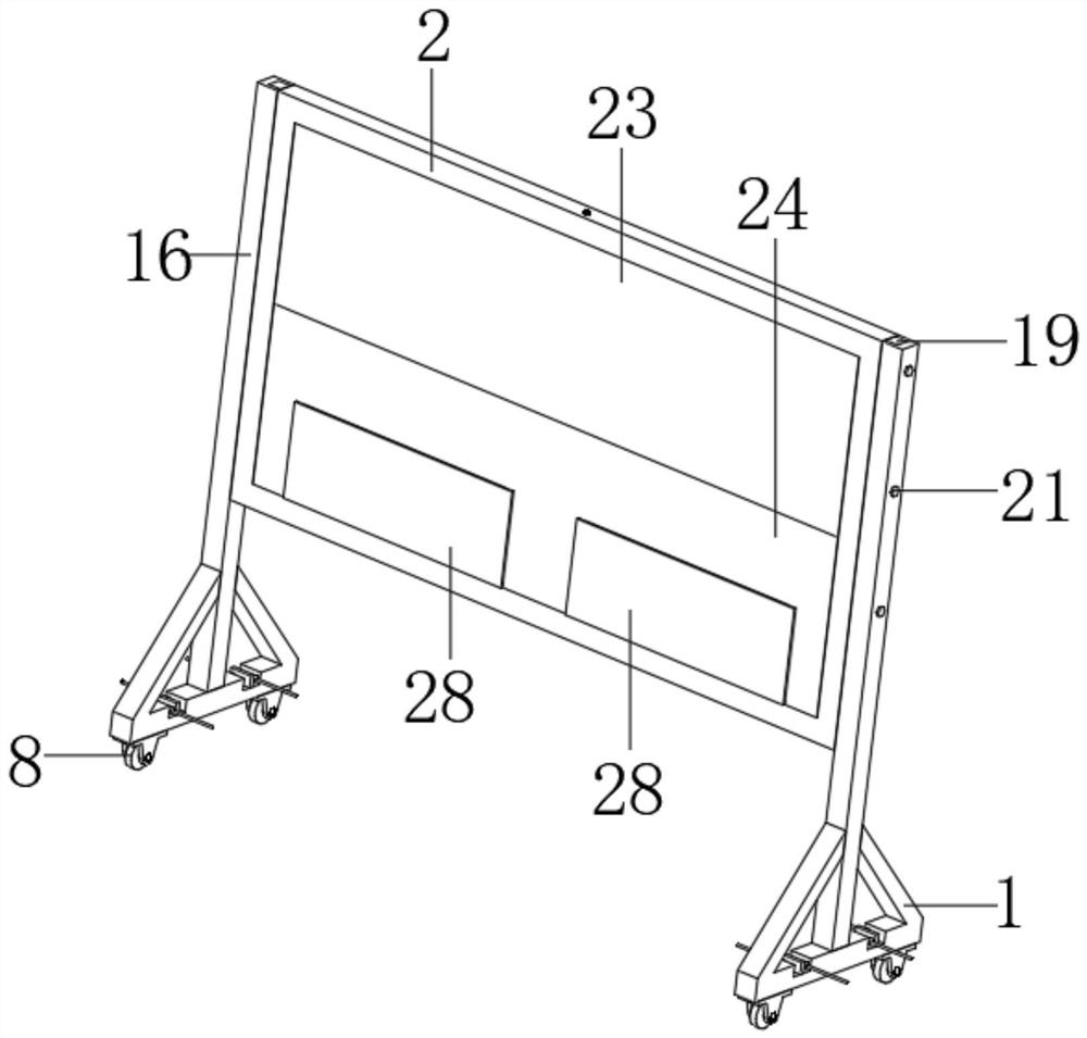
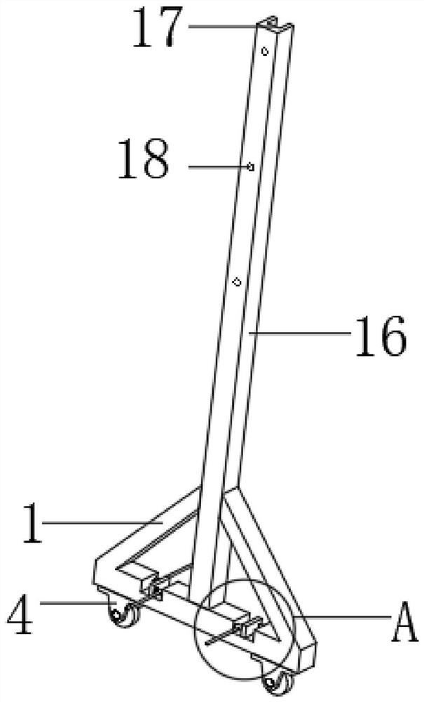
[0043] Such as figure 1 , figure 2 with Figure 5 As shown, an auxiliary appliance for architectural design includes a mobile installation assembly and an indicator board 2, and the mobile installation assembly includes a tripod base 1, a connecting plate 4, a rotating shaft 7, a moving wheel 8, a vertical plate 16, an installation moment groove 17, Thread perforation 18, mounting plate 19, mounting screw hole 20 and mounting bolt 21; connecting plate 4 is arranged on the bottom of tripod 1 and includes a vertical part and a horizontal part, rotating shaft 7 runs through connecting plate 4 vertical parts, moves Wheel 8 is fixed on rotating shaft 7 ends, vertical plate 16 is fixed on the top center of triangular underframe 1 horizontal part, and installation moment groove 17 is arranged on the top of vertical plate 16 side, and installation moment groove 17 runs through vertical plate 16 side and top and is arranged, installs The bottom end of the moment groove 17 is arrange...
Embodiment 2
[0046] Embodiment 2 is a further improvement to Embodiment 1:
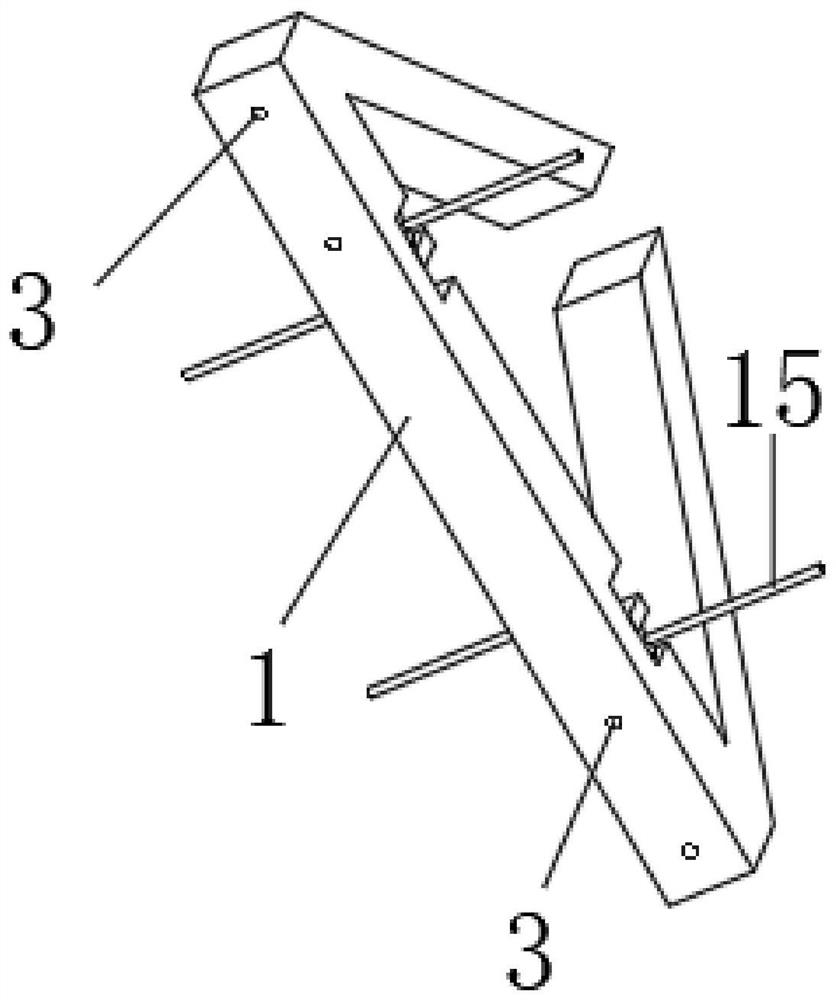
[0047] Such as image 3 , Figure 4 , Image 6 , Figure 7 , Figure 9 , Figure 10 , Figure 12 , Figure 13 , Figure 14 with Figure 15 The center of the bottom end of the horizontal part of the triangular chassis 1 shown is symmetrically provided with connecting holes 3 on both sides, the horizontal part of the connecting plate 4 cooperates with the connecting hole 3 to be provided with a through hole 5, and the through hole 5 and the connecting hole 3 are threadedly connected with a connecting screw 6; An indicator groove 22 is provided in the center of the side of the indicator plate 2, and an indicator adjustment component is arranged inside the indicator groove 22. The indicator adjustment component includes a transparent plate 23, a sealing plate 24, an opening 25, an adjustment chute 29, an adjustment slider 30, and a pasting plate 33 , magnetic paste 34, collar 36, hidden groove 37, backing pla...
Embodiment 3
[0049] Embodiment 3 is a further improvement to embodiment 2:
[0050] Such as Figure 7 , Figure 8 , Figure 10 with Figure 11 As shown, the two sides of the opening 25 are symmetrically provided with chute 26, the inside of the chute 26 slides with a slider 27, the end of the slider 27 is fixed with a closing plate 28, and the top and bottom of the chute 26 are respectively connected with the top and bottom of the opening 25. The ends are flush, the height of the closing plate 28 is equal to the height of the opening 25, a buffer rod 31 is fixed on the lower wall of the indicator groove 22, a buffer spring 32 is provided at the bottom end of the side wall of the buffer rod 31, and a buffer spring 32 is provided at the bottom of the paste plate 33 at the center of the bottom end. The jack that the rod 31 cooperates, the inner wall of the indicating groove 22 is symmetrically provided with an L-shaped corner block 35, the inner side of the corner of the L-shaped corner bl...
PUM
 Abstract
Description
Claims
Application Information
 - R&D
- Intellectual Property
- Life Sciences
- Materials
- Tech Scout
- Unparalleled Data Quality
- Higher Quality Content
- 60% Fewer Hallucinations
Browse by: Latest US Patents, China's latest patents, Technical Efficacy Thesaurus, Application Domain, Technology Topic, Popular Technical Reports.
© 2025 PatSnap. All rights reserved.Legal|Privacy policy|Modern Slavery Act Transparency Statement|Sitemap|About US| Contact US: help@patsnap.com


