Dish washing machine with automatic water feeding function
A technology of automatic water inlet and dishwasher, applied in the direction of tableware washing machine/rinsing machine, tableware washing machine/rinsing and rinsing machine parts, cleaning equipment, etc., which can solve the limited folding space of dishwashers and the structure of dishwashers Complicated, not convenient to carry and other problems, to achieve the effect of low manufacturing cost, low working noise, easy to carry
- Summary
- Abstract
- Description
- Claims
- Application Information
AI Technical Summary
Problems solved by technology
Method used
Image
Examples
Embodiment 1
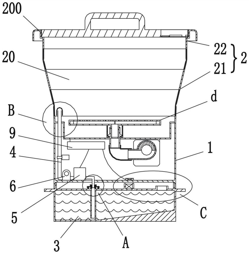
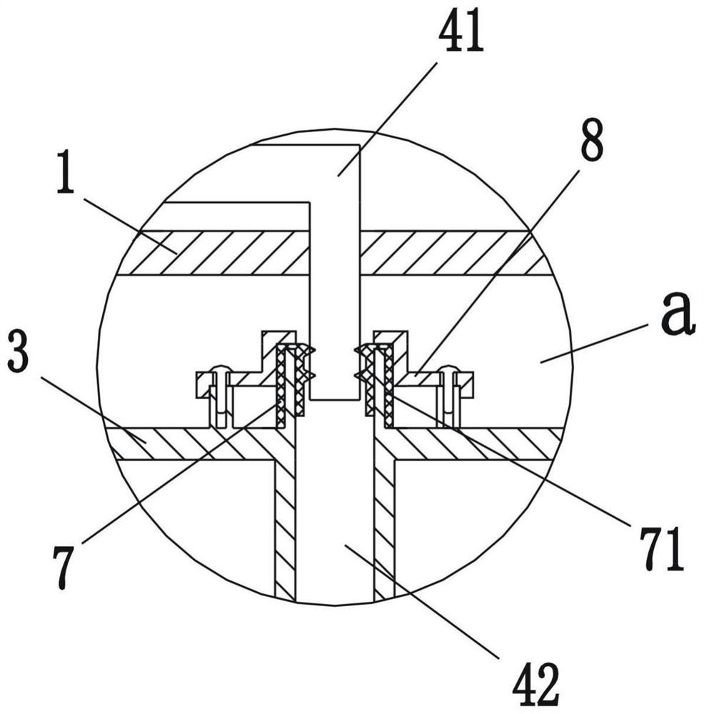
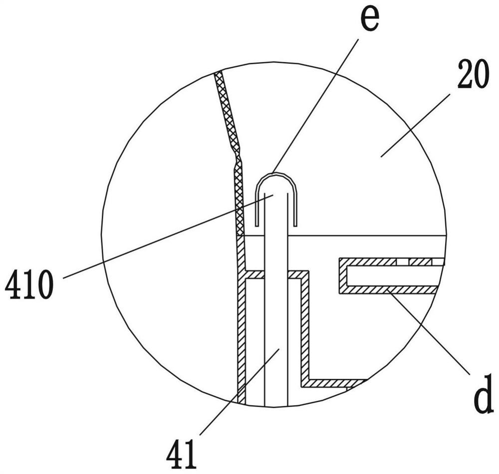
[0034] Such as figure 1 , figure 2 , image 3 , Figure 4 , Figure 5 Shown is a schematic structural view of an embodiment of the dishwasher of the present invention. A dishwasher, comprising a base 1 and a foldable housing 2, the lower end of the housing 2 is hermetically connected to the base 1, and the upper end has an opening 200, the housing 2 and the base 1 enclose a cleaning chamber chamber 20, and a spraying device d is installed in the cleaning chamber 20, the housing 2 includes a foldable connecting ring 21 and a supporting ring 22 fixed on the upper end of the connecting ring 21, and a closed opening is installed on the supporting ring 22 200 cover (not marked in the figure), the bottom of the base 1 is provided with a detachable water tank 3, and the water tank 3 communicates with the cleaning chamber 20 through the communication pipe 4, wherein the communication pipe 4 is installed with The water pump 5 that pumps the cleaning water in the water tank 3 into...
Embodiment 2
[0048] Such as Figure 6 , Figure 7 Shown is a schematic structural diagram of the second embodiment of the present invention. The difference between this embodiment and Embodiment 1 is: in this embodiment, the water tank 3 has a water storage chamber 32 and an auxiliary installation chamber 33, wherein the water storage chamber 32 and the auxiliary installation chamber 33 are separated by a separation plate 34 , wherein, the isolation plate 34 is integrally formed on the water tank 3, and the water pump 5 and the second communication pipe 42 are installed in the auxiliary installation cavity 33, and the second communication pipe 42 runs through the isolation plate 34 and extends into the water tank. The bottom of cavity 32. At the same time, a first coupler f1 electrically connected to the control device 9 is installed on the outside of the bottom wall of the base 1, and a second coupler f2 electrically connected to the water pump 5 is installed on the outside of the top w...
Embodiment 3
[0053] Such as Figure 8 , Figure 9 Shown is a schematic structural view of the third embodiment of the present invention. The difference between this embodiment and the above embodiments is that in this embodiment, the width of the water tank 3 is greater than the width of the base 1, and a water filling hole 38 is provided on the top wall of the water tank 3, wherein the base 1 is installed on When the water tank 3 was on, the water filling hole 38 was exposed on the outside of the base 1 . Moreover, an exhaust groove 37 is also provided at the installation joint between the water tank 3 and the base 1, so that when the user adds water from the water filling hole 38 to the water tank 3, the air in the installation interlayer a can be discharged through the exhaust groove 37.
[0054] This embodiment also has the same beneficial effect as the above embodiment, which will not be repeated here.
PUM
 Abstract
Description
Claims
Application Information
 - R&D
- Intellectual Property
- Life Sciences
- Materials
- Tech Scout
- Unparalleled Data Quality
- Higher Quality Content
- 60% Fewer Hallucinations
Browse by: Latest US Patents, China's latest patents, Technical Efficacy Thesaurus, Application Domain, Technology Topic, Popular Technical Reports.
© 2025 PatSnap. All rights reserved.Legal|Privacy policy|Modern Slavery Act Transparency Statement|Sitemap|About US| Contact US: help@patsnap.com


