Plant irrigation platform for rock ecological restoration

An ecological restoration and plant technology, applied in the fields of botany equipment and methods, application, horticulture, etc., can solve the problem of single function of plant irrigation platform, and achieve the effect of realizing flow, realizing regulation and preventing water hammer effect.

Inactive Publication Date: 2021-06-18
王洪亮
View PDF11 Cites 2 Cited by
  • Summary
  • Abstract
  • Description
  • Claims
  • Application Information

AI Technical Summary

Problems solved by technology

[0002] The plant irrigation platform for rock ecological restoration is a commonly used equipment in the field of rock ecological restoration, but the general function of the plant irrigation platform for rock ecological restoration is relatively single

Method used


Image

  • Plant irrigation platform for rock ecological restoration
  • Plant irrigation platform for rock ecological restoration
  • Plant irrigation platform for rock ecological restoration

Examples


specific Embodiment approach 1

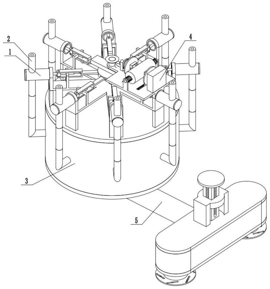
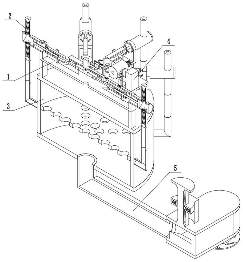
[0034] Combine below Figure 1-16 Description of this embodiment, a plant irrigation platform for rock ecological restoration, including a gas booster assembly 1, a one-way valve assembly 2, a water tank assembly 3, a power assembly 4, and a spout assembly 5, the gas booster The valve assembly 2 is connected, the one-way valve assembly 2 is connected with the water tank assembly 3 , the gas booster assembly 1 is connected with the power assembly 4 , and the spout assembly 5 is connected with the water tank assembly 3 .

specific Embodiment approach 2

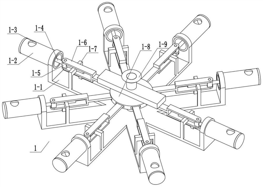
[0036] Combine below Figure 1-16 Describe this embodiment, this embodiment will further explain the first embodiment, the gas booster assembly 1 includes a booster bracket 1-1, a cylinder 1-2, a mounting hole 1-3, a piston rod 1-4, and a hinged terminal 1-5, hinged rotating rod 1-6, auxiliary bracket 1-7, eccentric drive plate 1-8, bevel gear 1-9, drive terminal 1-10, spherical clamping rod 1-11, spherical clamping rod push spring 1 -12, drive turret 1-13, spherical card slot one 1-14, installation hole two 1-15, the cylinder 1-2 is fixedly connected with booster support 1-1, installation hole one 1-3, installation hole Both 1-15 are arranged on the cylinder 1-2, the piston rod 1-4 is slidingly connected with the cylinder 1-2, the inner end of the cylinder 1-2 is hollowed out, and the hinged terminal 1-5 is fixedly connected with the piston rod 1-4, hinged One end of the rotating rod 1-6 is hingedly connected to the hinge terminal 1-5, the other end of the hinged rotating ro...

specific Embodiment approach 3

[0038] Combine below Figure 1-16 Describe this embodiment, this embodiment will further explain the first embodiment, the one-way valve assembly 2 includes an inlet valve sleeve 2-1, a one-way ball 2-2, an outlet valve sleeve 2-3, and a connecting plate One 2-4, one-way push spring one 2-5, one-way ball two 2-6, through hole one 2-7, connecting plate two 2-8, one-way push spring two 2-9, through hole two 2- 10. The second through hole 2-10 is set on the air valve casing 2-1, the one-way ball 2-2 is connected with the second through hole 2-10, and the connecting plate two 2-8 is connected with the air valve casing 2 -1 is fixedly connected, the one-way push spring two 2-9 is arranged between the one-way ball one 2-2 and the connecting plate two 2-8, the connecting plate one 2-4 is fixedly connected with the outlet valve casing 2-3, and the Hole one 2-7 is arranged on the outlet valve casing 2-3, one-way ball two 2-6 is connected with through hole one 2-7, and one-way push spr...


PUM


Abstract

The invention relates to the field of rock ecological restoration, in particular to a plant irrigation platform for rock ecological restoration, and can realize plant restoration liquid irrigation on plants. The platform comprises a gas pressurization assembly, a one-way valve assembly, a water tank assembly, a power assembly and a nozzle assembly, wherein under the action of air, plant restoration liquid flows into a liquid cavity through a connecting pipe, liquid diversion is achieved through a liquid diversion boss, the water hammer effect is prevented, the plant restoration liquid obtained after liquid diversion flows out through a spray pipe, the plants are irrigated, and meanwhile, a manual rotating rod and the spray pipe are relatively rotated, so that the area between adjusting plates is changed, and the flow of the plant restoration liquid discharged in unit time is adjusted.

Description

technical field [0001] The invention relates to the field of rock ecological restoration, in particular to a plant irrigation platform for rock ecological restoration. Background technique [0002] The plant irrigation platform for rock ecological restoration is a commonly used equipment in the field of rock ecological restoration, but the general function of the plant irrigation platform for rock ecological restoration is relatively single. Contents of the invention [0003] The purpose of the present invention is to provide a plant irrigation platform for ecological restoration of rocks, which can realize the irrigation of plants with phytoremediation liquid. [0004] The purpose of the present invention is achieved through the following technical solutions: [0005] A plant irrigation platform for rock ecological restoration, comprising a gas booster assembly, a one-way valve assembly, a water tank assembly, a power assembly, and a spout assembly, the gas booster assem...

Claims


Application Information

Patent Timeline
Patent Type & Authority Applications(China)
IPC IPC(8): B05B9/047B05B12/00A01G7/06
CPCB05B9/047B05B12/002A01G7/06
Inventor 王洪亮
Owner 王洪亮
Why Eureka
Try Eureka