Pay-off device
A technology of pay-off device and sliding assembly, which is applied in the direction of transportation and packaging, delivery of filamentous materials, thin material processing, etc., which can solve problems such as cable accumulation, safety hazards, and damage to cable structures, so as to improve laying quality and improve laying quality. efficiency effect
- Summary
- Abstract
- Description
- Claims
- Application Information
AI Technical Summary
Problems solved by technology
Method used
Image

Examples
Embodiment 1
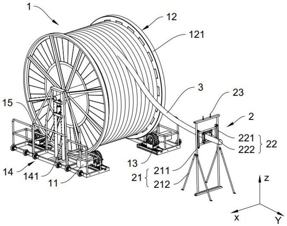
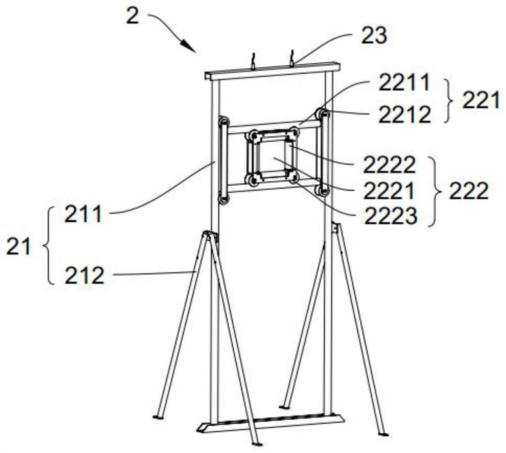
[0044] Such as Figure 1-4As shown, the present embodiment provides a pay-off device, including a drive mechanism 1 and a measurement and control mechanism 2, the drive mechanism 1 is used to drive the cable 3 to pay off; the measurement and control mechanism 2 includes a first bracket 21, a The sliding assembly 22 and the sensor 23, the sliding assembly 22 can slide on the first support 21 along the first direction (i.e. the Z direction in the drawings), the second direction (i.e. the X direction in the drawings), the free end of the cable 3 Pass through the sliding assembly 22 and be connected with the traction device. When the pulling speed of the cable 3 is not equal to the pay-off speed of the cable 3, the position of the sliding assembly 22 on the first support 21 changes; the sensor 23 is used to detect the sliding assembly 22 The position on the first support 21; the measurement and control mechanism 2 also includes a control module, the control module is used to recei...
Embodiment 2
[0057] This embodiment provides a wire pay-off device. Compared with Embodiment 1, the basic structure of the wire pay-off device provided by this embodiment is the same as Embodiment 1, except that the height of the crossbar 142 on the second bracket 14 is adjustable. different.
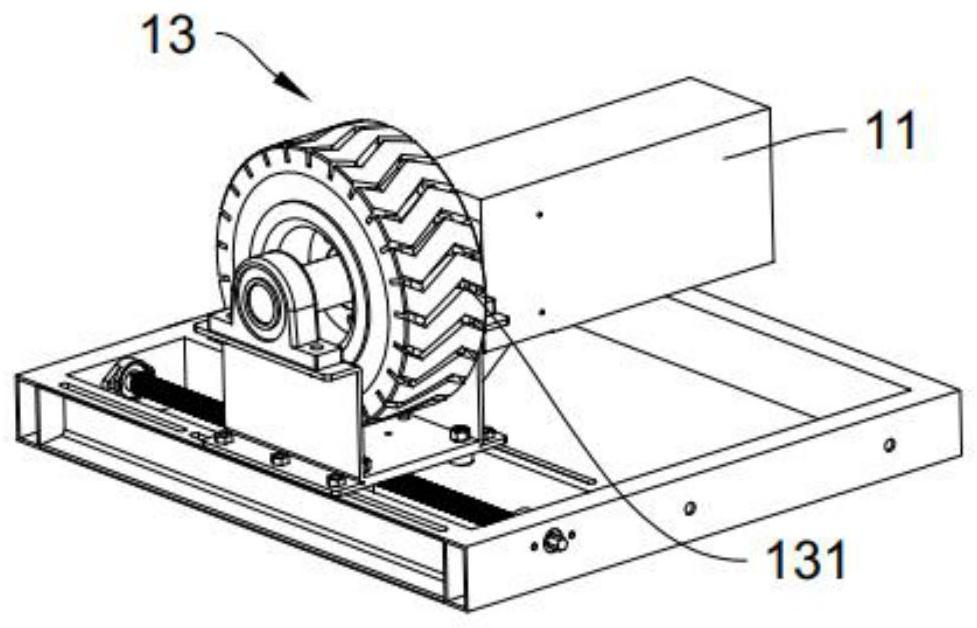
[0058] Such as Figure 4 As shown, optionally, the second bracket 14 is also provided with a second driving member 144, the driving direction of the second driving member 144 is the vertical direction, and the cross bar 142 is arranged at the output end of the second driving member 144, thereby realizing The height of the cross bar 142 on the second support 14 is adjustable. Further optionally, both ends of the cross bar 142 are provided with arc-shaped slots, and the inner wall of the arc-shaped slot fits with the outer wall of the vertical bar 141 to realize the stable movement of the cross bar 142 .
PUM
 Abstract
Description
Claims
Application Information
 - Generate Ideas
- Intellectual Property
- Life Sciences
- Materials
- Tech Scout
- Unparalleled Data Quality
- Higher Quality Content
- 60% Fewer Hallucinations
Browse by: Latest US Patents, China's latest patents, Technical Efficacy Thesaurus, Application Domain, Technology Topic, Popular Technical Reports.
© 2025 PatSnap. All rights reserved.Legal|Privacy policy|Modern Slavery Act Transparency Statement|Sitemap|About US| Contact US: help@patsnap.com