Optical lens

An optical lens and lens technology, applied in the field of optical lenses, can solve problems such as difficult to meet the requirements of consumers, and achieve the effect of compact structure, wide range of shooting scenes, and high pixel balance.

Active Publication Date: 2021-06-18
JIANGXI LIANYI OPTICS CO LTD
View PDF2 Cites 2 Cited by
  • Summary
  • Abstract
  • Description
  • Claims
  • Application Information

AI Technical Summary

Problems solved by technology

In recent years, as consumers have become more and more fond of cameras, the requirements for camera lenses on portable electronic devices have also become higher and higher. While pursuing high-pixel, high-definition imaging, there are also improvements in imaging and imaging effects in different scenarios. Certain considerations; at the same time, under the trend of increasingly thinner and lighter portable electronic devices, there are also great requirements for the total length of the camera lens, and it is difficult for ordinary camera lenses to meet the requirements of consumers

Method used


Image

  • Optical lens
  • Optical lens
  • Optical lens

Examples


no. 1 example

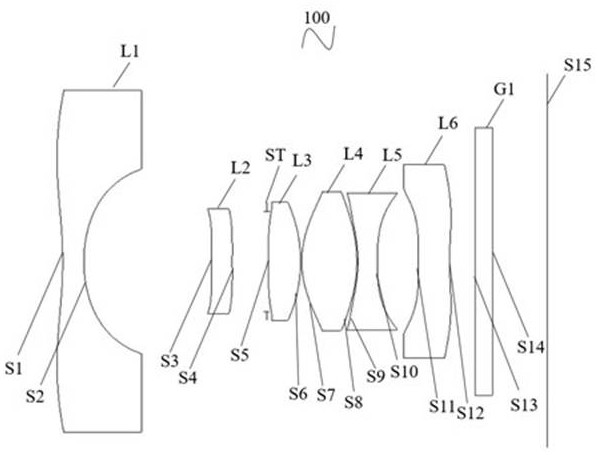
[0088] For the structural schematic diagram of the optical lens 100 provided by the first embodiment of the present invention, please refer to figure 1 , the optical lens 100 along the near optical axis direction from the object side to the image side is: the first lens L1, the second lens L2, the stop ST, the third lens L3, the fourth lens L4, the fifth lens L5 and the sixth lens Lens L6.

[0089] The first lens L1 is a plastic aspheric lens with negative refractive power, the object side S1 of the first lens is concave at the near optical axis, and the image side S2 of the first lens is concave at the near optical axis;

[0090] The second lens L2 is a plastic aspheric lens with positive refractive power, the object side S3 of the second lens is convex at the near optical axis, and the image side S4 of the second lens is concave at the near optical axis;

[0091] The third lens L3 is a plastic aspheric lens with positive refractive power, the object side S5 of the third len...

no. 2 example

[0105] For the structural schematic diagram of the optical lens 200 provided in this embodiment, please refer to Figure 6 , the structure of the optical lens 200 in this embodiment is quite different from that of the optical lens 100 in the first embodiment, wherein the second lens L2 and the fifth lens L5 are thicker, and the second lens L2, the fifth lens L5 and the fifth lens The six-lens L6 unevenness is more obvious. The optical lens 200 is sequentially arranged from the object side to the image side along the near optical axis direction: the first lens L1, the second lens L2, the diaphragm ST, the third lens L3, the fourth lens L4, the fifth lens L5 and the sixth lens L6.

[0106] The first lens L1 is a plastic aspheric lens with negative refractive power, the object side S1 of the first lens is concave at the near optical axis, and the image side S2 of the first lens is concave at the near optical axis;

[0107] The second lens L2 is a plastic aspheric lens with posi...

no. 3 example

[0122] For the structural schematic diagram of the optical lens 300 provided in this embodiment, please refer to Figure 11 , the main difference between the structure of the optical lens 300 in the present embodiment and the structure of the optical lens 100 in the first embodiment is that: the radius of curvature of the first lens object side and the image side are different, and the second lens L2, the fifth lens The concavity and convexity of L5 and the sixth lens L6 are more obvious. The optical lens 300 along the near optical axis direction from the object side to the image side includes: first lens L1, second lens L2, diaphragm, third lens L3, fourth lens L4, fifth lens L5 and sixth lens L6 .

[0123] The first lens L1 is a plastic aspheric lens with negative refractive power, the object side S1 of the first lens is concave at the near optical axis, and the image side S2 of the first lens is concave at the near optical axis;

[0124] The second lens L2 is a plastic as...


PUM


Abstract

The invention provides an optical lens, which sequentially comprises, from an object side surface to an imaging surface, a first lens with negative focal power, wherein the objective side and the image side near the optical axis are both concave surfaces; a second lens with positive focal power; a diaphragm; a third lens with positive focal power, wherein the image side of the third lensnear the optical axis is a convex surface; a fourth lens with positive focal power, wherein the object side and the image side of the fourth lens near the optical axis are convex surfaces; a fifth lens with negative focal power; and a sixth lens with negative focal power, wherein the image side of the sixth lens near the optical axis is a concave surface, wherein the FOV of the optical lens is greater than 150 degrees; the distance TTL from the object side to the image of the first lens of the optical lens is less than 5.8 mm.

Description

technical field [0001] The invention relates to the technical field of lens imaging, in particular to an optical lens. Background technique [0002] At present, with the improvement of the quality of life of the people, electronic consumer products are becoming more and more popular, and portable electronic devices (such as smart phones, tablet computers, etc.) naturally become consumers' primary considerations. With the rise of live streaming, social networking, and video software, consumers are paying more and more attention to the effects of taking pictures and taking pictures. Therefore, mobile phone camera lenses have become one of the primary considerations for consumers when purchasing electronic devices. [0003] With the continuous development of mobile information technology, portable electronic devices such as mobile phones are also developing in the direction of ultra-thin, ultra-high-definition imaging, and imaging diversification, which puts higher demands on t...

Claims


Application Information

Patent Timeline
Patent Type & Authority Applications(China)
IPC IPC(8): G02B13/00G02B13/18
CPCG02B13/0015G02B13/0045
Inventor 王义龙刘绪明曾昊杰徐文曾吉勇
Owner JIANGXI LIANYI OPTICS CO LTD
Why Eureka
Try Eureka