Baby seat capable of rotatably adjusting height of backrest
A baby seat and swivel technology, which is applied in the direction of children's chairs, children's furniture, household appliances, etc., can solve the problems of uncomfortable use, insufficient backrest coverage, and adjustment of backrest height, so as to achieve easy operation and increase the versatility of use Effect
- Summary
- Abstract
- Description
- Claims
- Application Information
AI Technical Summary
Problems solved by technology
Method used
Image

Examples
Embodiment 1
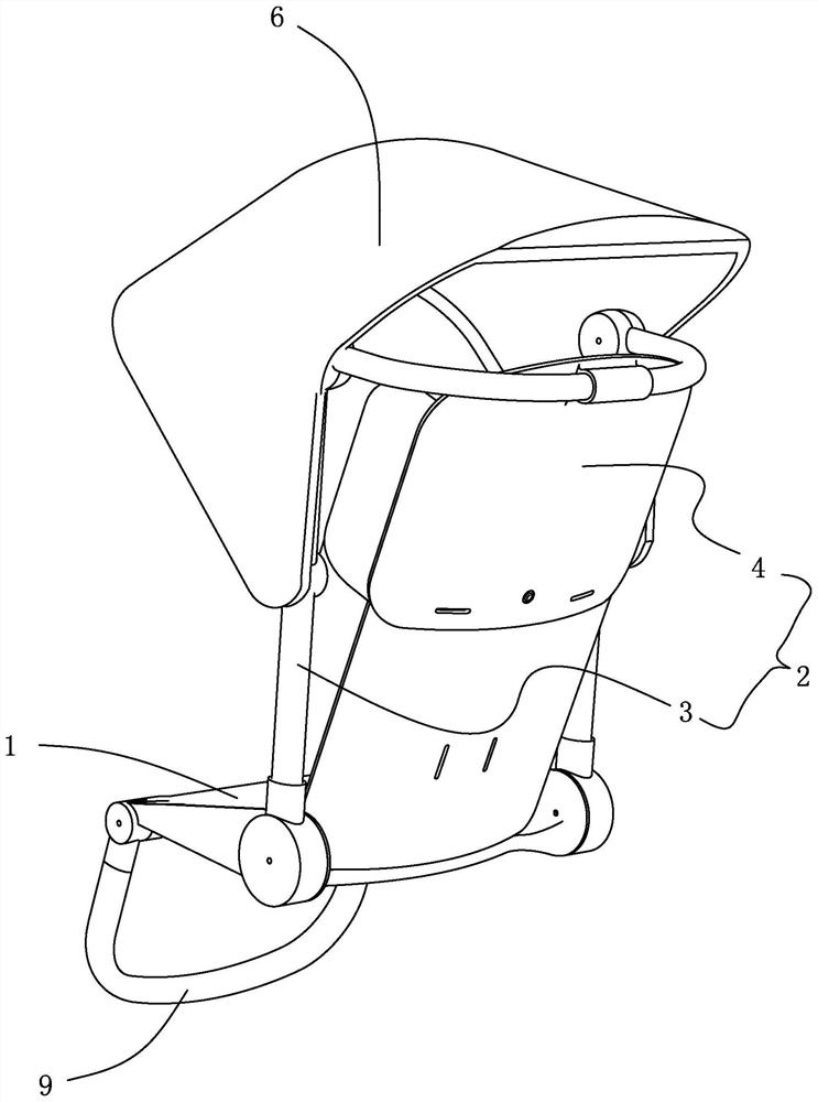
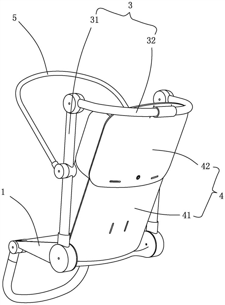
[0047] Embodiment one: if Figure 1 to Figure 7 As shown, the infant seat with rotary adjustable backrest height includes seat 1 and backrest group 2. The backrest group 2 extends backward and upward from the rear end of the seat 1, the backrest group 2 and the seat 1 form a bearing area, and the backrest group 2 includes a support frame 3 and a backrest support portion with a variable extension height 4. The support frame 3 is arranged at the rear end of the seat 1, and the support frame 3 includes a lower shaft connecting pipe 31 and an upper shaft connecting pipe 32, and the lower shaft connecting pipe 31 extends backward and upward from the rear end of the seat 1, The upper shaft connecting pipe 32 is pivotally connected to the upper end of the lower shaft connecting pipe 31; the back support part 4 can be arranged at an angle with the lower shaft connecting pipe 31, and one side of the back supporting part 4 is connected to the The upper shaft connecting pipe 32 is conn...
Embodiment 2
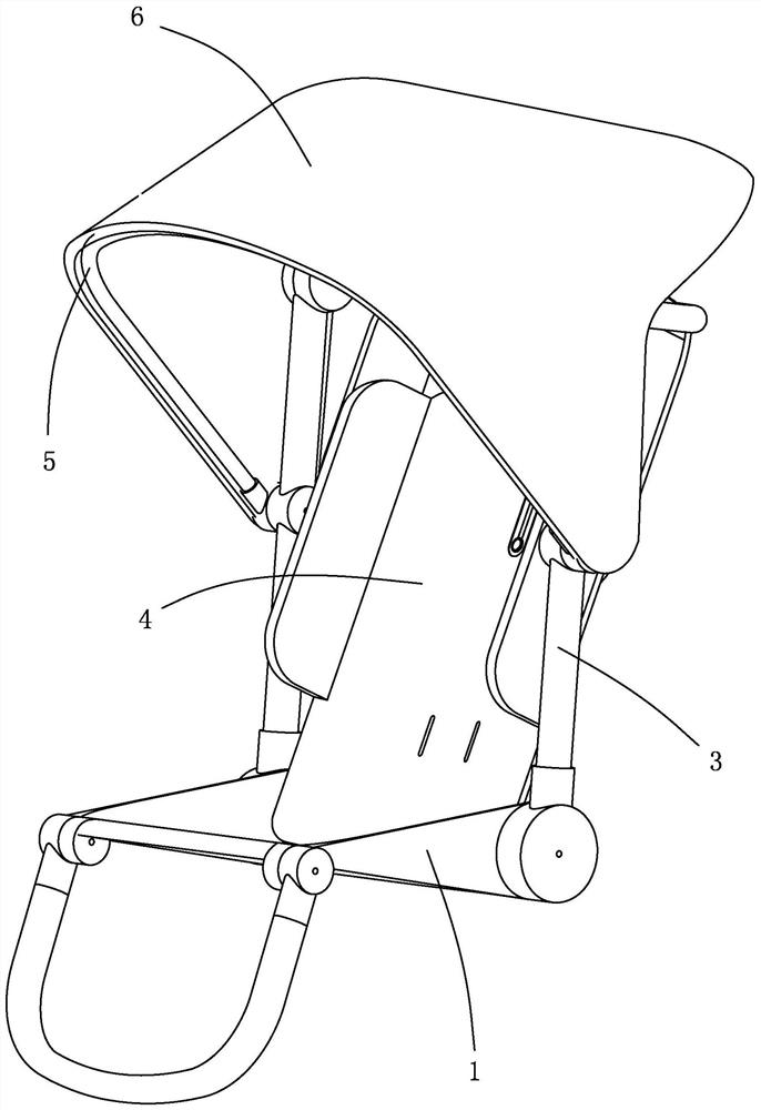
[0058] Embodiment two: if Figure 8 to Figure 10 As shown, the difference between this embodiment and the first embodiment is that the roof frame 5 is connected to the back support part 4, and when the upper shaft connecting pipe 32 rotates relative to the lower shaft connecting pipe 31 to change the included angle , the canopy frame 5 can move with the back support part 4 . The roof frame 5 can move with the backrest support portion, so that the roof frame 5 can be used to help the children who sit in the most suitable position to shade all the time.
[0059] Specifically, in order to facilitate the movement of the roof frame, the roof frame 5 is slidably connected to the support frame 3, and a linkage rod 7 is pivotally connected between the roof frame 5 and the back support part 4, so that The linkage rod 7 can rotate with the change of the included angle, and then push the roof frame 5 to slide along the support frame 3 . In order to effectively link the movement of the ...
Embodiment 3
[0060] Embodiment three: as Figure 11 and Figure 12 As shown, the difference between the present embodiment and the first embodiment is that the backrest support part 4 is an elastic software, which can change the stretching height with the rotation of the upper shaft connecting tube 32 . The height extension and change of the backrest supporting part can be realized by adopting elastic software, the structure is simple, and the use is convenient.
PUM
 Abstract
Description
Claims
Application Information
 - R&D
- Intellectual Property
- Life Sciences
- Materials
- Tech Scout
- Unparalleled Data Quality
- Higher Quality Content
- 60% Fewer Hallucinations
Browse by: Latest US Patents, China's latest patents, Technical Efficacy Thesaurus, Application Domain, Technology Topic, Popular Technical Reports.
© 2025 PatSnap. All rights reserved.Legal|Privacy policy|Modern Slavery Act Transparency Statement|Sitemap|About US| Contact US: help@patsnap.com