Steel cord back thread protection suction detection device

A detection device and protection device technology, applied in the direction of magnetic performance measurement, etc., can solve the problems of inability to pass, large blindness, large error, etc., and achieve the effect of reducing hidden dangers in quality and improving detection accuracy.

Inactive Publication Date: 2021-06-22
JIANGSU XINGDA STEEL TYPE CORD
View PDF8 Cites 0 Cited by
  • Summary
  • Abstract
  • Description
  • Claims
  • Application Information

AI Technical Summary

Problems solved by technology

[0003] The back wire protection is composed of the upper fixed detection piece and the lower movable detection piece. Each of the two detection pieces has a semicircular hole equal to 110% of the cord thickness. The cord passes through the middle of the two detection pieces. When the machine tool is running normally The movable detection piece is absorbed by strong magnetism, and combined with the fixed detection piece to form a full circle equal to 110% of the thickness of the cord of this specification. Once the cord has defects such as broken wires, back wires, and exposed cores, its diameter must be larger than the cord Thickness, unable to pass through the round hole of the combination of the two detection pieces, causing the activity detection piece to flip down and touch the copper column connected to the machine tool alarm stop line under the back wire protection
There is a strong magnet embedded in the back wire protection bracket, and the strong magnet will absorb the detection piece on the bracket. If the adsorption force is too large, the detection piece will not move when some back wire passes through, and there will be missed detection. If the adsorption force is too small, it will cause false detection and affect Machine Tool Productivity
[0004] The disadvantage of the prior art is that the current strong magnetic adsorption force is realized by adjusting the distance between the detection piece and the strong magnetism. At present, the detection piece is pulled by hand, and the adsorption force is adjusted by experience. The suction force between the strong magnet and the activity detection piece cannot be quantified digitally. The staff can detect the size of the suction force by hand feeling. When the suction force is small, move the strong magnet forward a little closer to the activity detection sheet. The adjustment process is relatively blind and the error is relatively large, and digital quantitative management cannot be realized.

Method used


Image

  • Steel cord back thread protection suction detection device
  • Steel cord back thread protection suction detection device
  • Steel cord back thread protection suction detection device

Examples


Embodiment Construction

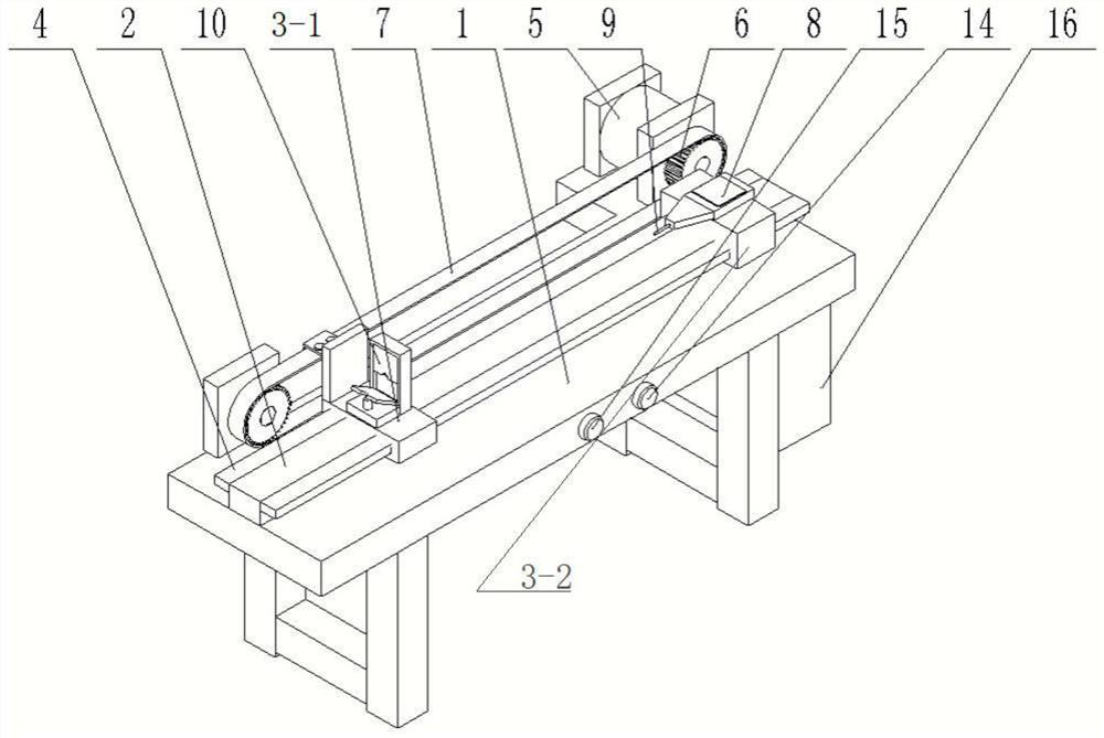
[0022] The present invention will be further described below in conjunction with the accompanying drawings. The following examples are only used to illustrate the technical solution of the present invention more clearly, but not to limit the protection scope of the present invention.

[0023] In describing the present invention, it should be understood that the terms "center", "longitudinal", "transverse", "upper", "lower", "front", "rear", "left", "right", " The orientations or positional relationships indicated by "vertical", "horizontal", "top", "bottom", "inner" and "outer" are based on the orientations or positional relationships shown in the drawings, and are only for the convenience of describing the present invention and Simplified descriptions, rather than indicating or implying that the device or element referred to must have a particular orientation, be constructed and operate in a particular orientation, and thus should not be construed as limiting the invention. ...


PUM


Abstract

The invention discloses a steel cord back thread protection suction detection device which comprises a sliding part, a back thread protection device, a clamping groove device and a digital display dynamometer, and can quantify the suction force between a movable detection sheet and a strong magnet so as to accurately guide and adjust the size of the suction force, improve the detection precision, reduce potential quality hazards and reduce the production cost of enterprises.

Description

technical field [0001] The invention relates to a steel cord back wire protection suction detection device, which is suitable for detecting the steel cord back wire protection suction for tires and belongs to the technical field of detection. Background technique [0002] In the production process of steel cord, there will inevitably be unqualified products such as broken wires, back wires, and exposed cores. For this reason, various safety devices are installed on various models on the market. It is an effective method to improve the quality of steel cords by timely detecting back wires in the production of steel cords and processing and correcting them in a timely manner. [0003] The back wire protection is composed of the upper fixed detection piece and the lower movable detection piece. Each of the two detection pieces has a semicircular hole equal to 110% of the cord thickness. The cord passes through the middle of the two detection pieces. When the machine tool is run...

Claims


Application Information

Patent Timeline
Patent Type & Authority Applications(China)
IPC IPC(8): G01R33/12
CPCG01R33/12
Inventor 刘祥左树华刘湘慧袁兴华汤恒威
Owner JIANGSU XINGDA STEEL TYPE CORD
Why Eureka
Try Eureka