a boost converter

A technology of boost converter and comparator, which is applied in high-efficiency power electronic conversion, output power conversion devices, instruments, etc., can solve the problems of low conversion efficiency and achieve high conversion efficiency

Active Publication Date: 2022-07-12
SG MICRO
View PDF5 Cites 0 Cited by
  • Summary
  • Abstract
  • Description
  • Claims
  • Application Information

AI Technical Summary

Problems solved by technology

This brings up a problem, the conversion efficiency of VIN to VOUT is very low

Method used


Image

  • a boost converter
  • a boost converter

Examples


Embodiment Construction

[0016] Below in conjunction with the accompanying drawings ( Figure 1-Figure 2 ) to describe the present invention.

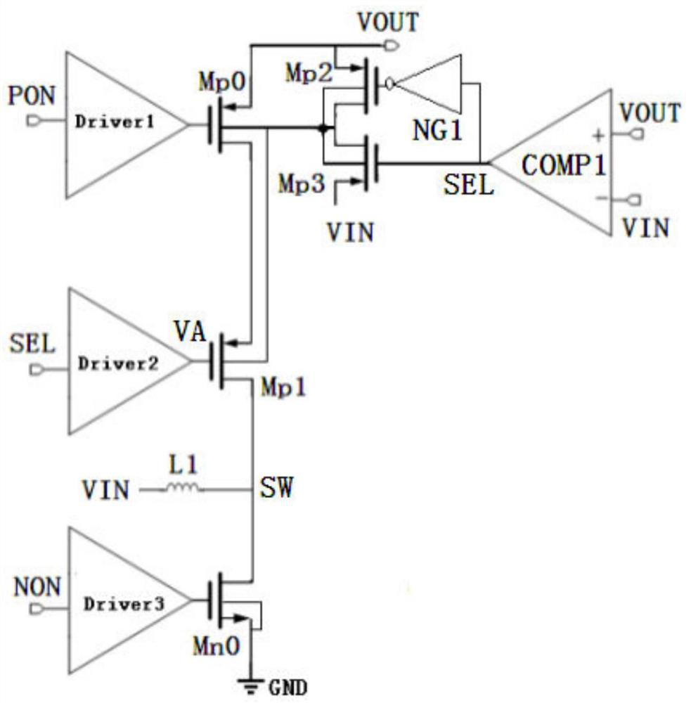
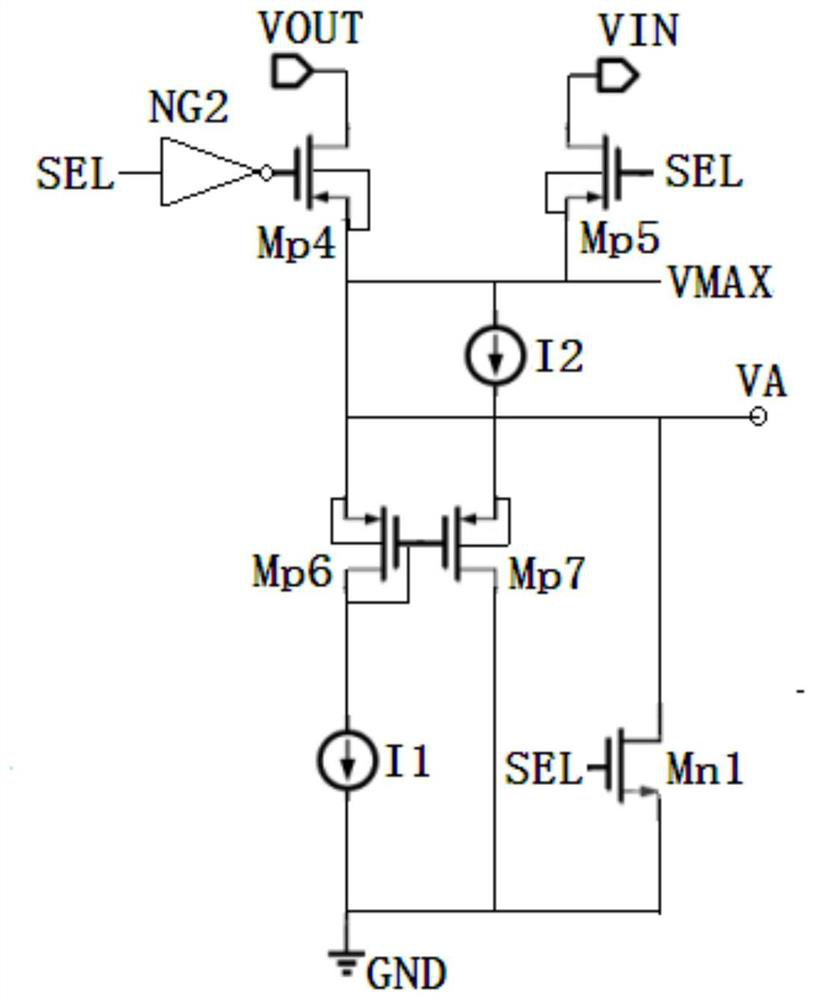
[0017] figure 1 It is a schematic diagram of the circuit structure of a boost converter implementing the present invention. figure 2 Yes figure 1 A schematic diagram of the circuit structure of the gate drive circuit Driver2 of the second PMOS transistor Mp1. refer to Figure 1 to Figure 2 As shown, a boost converter includes a first PMOS power switch Mp0 driven by a first control signal PON through a first drive circuit Driver1, and a first PMOS power switch Mp0 driven by a third control signal NON through a third drive circuit Driver3 NMOS transistor Mn0, a second PMOS power switch transistor Mp1 is introduced, the second PMOS power switch transistor Mp1 and the first PMOS power switch transistor Mp0 form a series combination, and the second PMOS power switch transistor Mp1 is controlled by the second The signal SEL is driven by the second driving circ...


PUM


Abstract

A boost converter, by setting the series combination of the second power switch tube Mp1 and the first power switch tube Mp0, not only can maintain normal boost, but also when the input voltage VIN is close to, equal to or greater than the output voltage VOUT, VOUT The ripple remains small to ensure regulated output and improve conversion efficiency.

Description

technical field [0001] The invention relates to DCDC conversion technology, in particular to a boost converter. By setting the series combination of the second power switch Mp1 and the first power switch Mp0, the normal boost can be maintained, and the input voltage VIN can be close to, When equal to or greater than the output voltage VOUT, the VOUT ripple remains small to ensure regulated output and improve conversion efficiency. Background technique [0002] A boost converter, also known as a Boost converter, is a common type of DCDC converter. DCDC (direct current-direct current) refers to the DC-to-DC conversion that changes the DC parameters. A boost converter typically boosts a lower input voltage VIN to a higher output voltage VOUT. However, during the boost conversion process, VIN can also be close to, equal to, or greater than VOUT. When this happens, the usual Boost converter will have problems with large ripple and unable to maintain output voltage regulation. ...

Claims


Application Information

Patent Timeline
Patent Type & Authority Patents(China)
IPC IPC(8): H02M3/158H02M1/14
CPCH02M3/158H02M1/14Y02B70/10
Inventor 于翔许晶其他发明人请求不公开姓名
Owner SG MICRO
Why Eureka
Try Eureka