Drive circuit and liquid crystal display apparatus

A driving circuit and liquid crystal display panel technology, which is applied to static indicators, instruments, etc., can solve the problems of large driving signal ripple and large ripple, and achieve the effect of high current stability and reduced ripple

Active Publication Date: 2015-11-25
TCL CHINA STAR OPTOELECTRONICS TECH CO LTD
View PDF7 Cites 2 Cited by
  • Summary
  • Abstract
  • Description
  • Claims
  • Application Information

AI Technical Summary

Problems solved by technology

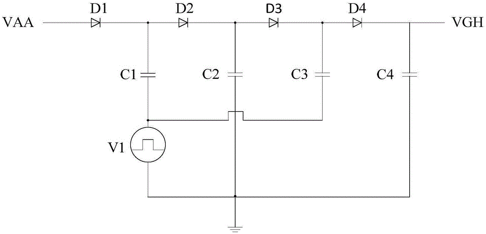
[0004] However, in this way, if the load of the input voltage VAA is low or the load changes greatly, the power management chip PWMIC will enter the DCM mode
In the DCM mode, that is, the inductor current discontinuous mode, in the DCM mode, the ripple of the driving signal LX1 will be very large, resulting in a very large ripple of the output voltage VGH

Method used


Image

  • Drive circuit and liquid crystal display apparatus
  • Drive circuit and liquid crystal display apparatus
  • Drive circuit and liquid crystal display apparatus

Examples


Embodiment Construction

[0022] The following will clearly and completely describe the technical solutions in the embodiments of the present invention with reference to the accompanying drawings in the embodiments of the present invention. Obviously, the described embodiments are only some, not all, embodiments of the present invention. Based on the embodiments of the present invention, all other embodiments obtained by persons of ordinary skill in the art without creative efforts fall within the protection scope of the present invention.

[0023] It should be noted that the terms used in the embodiments of the present invention are only for the purpose of describing specific embodiments, and are not intended to limit the present invention. As used in the embodiments of the present invention and the appended claims, the singular forms "a", "said" and "the" are also intended to include the plural forms unless the context clearly indicates otherwise. It should also be understood that the term "and / or" a...


PUM


Abstract

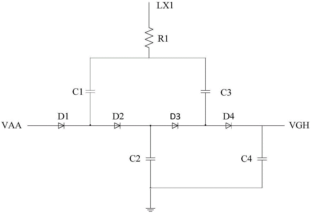
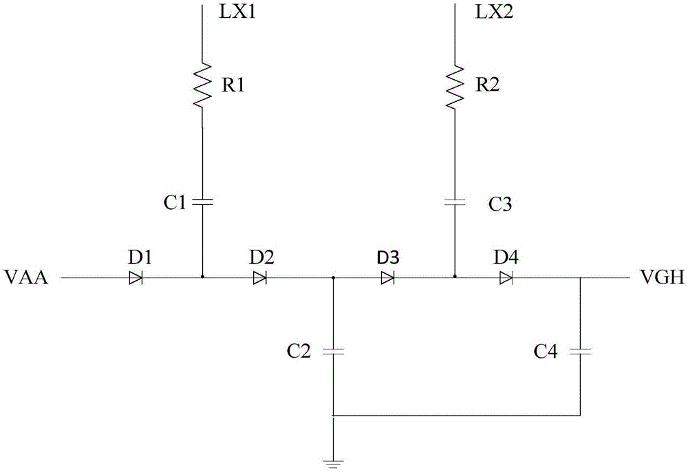
The present invention discloses a drive circuit and a liquid crystal display apparatus. The drive current comprises that: a first diode has an anode configured to input voltage and has a cathode configured to connect with an anode of a second diode; the second diode has a cathode configured to connect with an anode of a third diode; the third diode has a cathode configured to connect with an anode of a fourth diode; the fourth diode has a cathode configured to output voltage; a first capacitor has a first end configured to connect with the first diode and has a second end configured to connect with one end of a first resistor, the first resistor has the other one end configured to input a first driving signal; a second capacitor has one end configured to connect with the second diode and has the other end configured to connect with the ground; a third capacitor has one end configured to connect with the third diode and has the other end configured to connect with one end of a second resistor; the second resistor has the other end configured to input a second driving signal; and a fourth capacitor has one end configured to connect with the cathode of the fourth diode and has the other end configured to connect with the ground. The driving circuit provided by the invention is capable of reducing ripple waves of the output voltage.

Description

technical field [0001] The invention relates to the field of liquid crystal display, in particular to a driving circuit and a liquid crystal display device. Background technique [0002] Such as figure 1 As shown, the prior art provides a driving circuit, including a first diode D1, a second diode D2, a third diode D3, a fourth diode D4, a first capacitor C1, a second capacitor C2, the third capacitor C3, the fourth capacitor C4 and the input voltage source V1. Wherein, the anode of the first diode D1 is used for the input voltage VAA, the cathode of the first diode D1 is connected to the anode of the second diode D2, and the cathode of the second diode D2 is connected to the third diode D3. anode, the cathode of the third diode D3 is connected to the anode of the fourth diode D4, the cathode of the fourth diode D4 is used for the output voltage VGH, and the first end of the first capacitor C1 is connected to the first diode D1 and The common end of the second diode D2, t...

Claims


Application Information

Patent Timeline
IPC IPC(8): G09G3/36
CPCG09G3/3696G09G3/3648G09G2310/0213
Inventor 张先明
Owner TCL CHINA STAR OPTOELECTRONICS TECH CO LTD
Why Eureka
Try Eureka