Displacement metering pump and use of the displacement metering pump

A displacement metering and housing technology, applied in pumps, applications, kitchen utensils, etc., to achieve the effect of precise metering

Pending Publication Date: 2021-06-22
英达格包装合作有限公司
View PDF0 Cites 1 Cited by
  • Summary
  • Abstract
  • Description
  • Claims
  • Application Information

AI Technical Summary

Problems solved by technology

In addition, the flanged joint cannot be traversed by the piston seal of the displacement piston
Finally, there is also a dead zone above the product inlet and product outlet

Method used


Image

  • Displacement metering pump and use of the displacement metering pump
  • Displacement metering pump and use of the displacement metering pump

Examples


Embodiment Construction

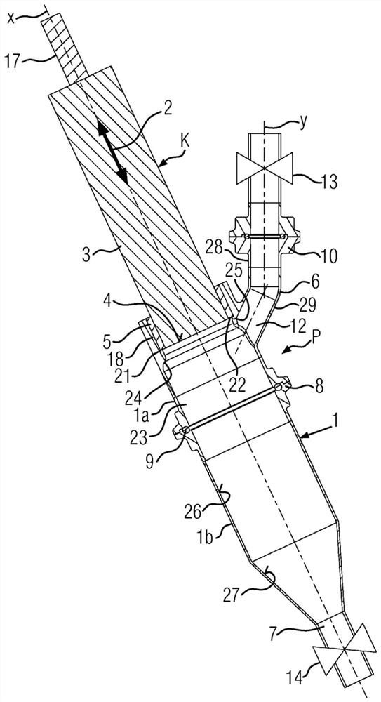
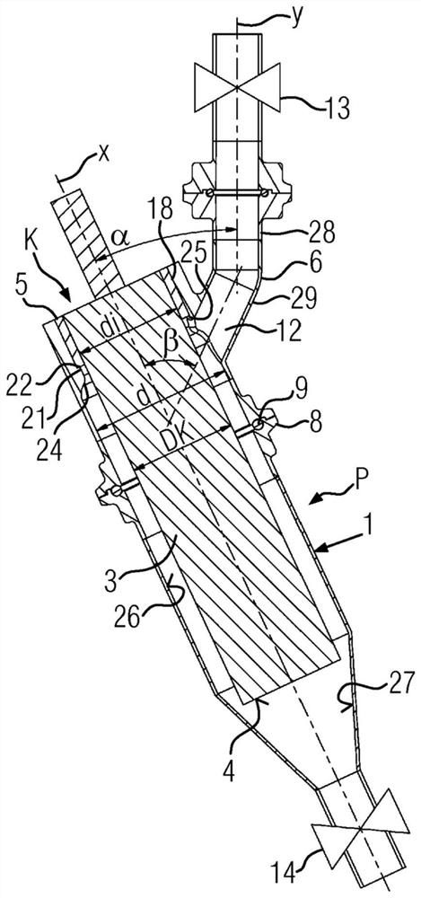
[0021] figure 1 and figure 2 Displacement metering pumps (displacement metering pumps) P, each of which is shown in cross-section, in particular displacement metering pumps for discrete volumetric metering of liquid to pasty products partially laden with solid matter, e.g. in the food industry The metering pump P can be mounted inclined in the operating position at an angle α of approximately 30°, for example, with respect to the vertical.

[0022] The displacement metering pump P includes, as main components, a tubular cartridge case 1 and a displacement piston K movable in the direction of the double arrow 2 inside the cartridge case 1 . The displacement piston K is embodied as a cylinder in its operating region and resembles a piston rod whose end 4 inside the cartridge housing 1 can be flat and substantially perpendicular to the cartridge axis X. The cartridge housing 1 is divided via a flange joint 8 with a seal 9 into a head 1 a and a bottom 1 b , where for example th...


PUM


Abstract

The invention relates to a displacement metering pump (P), comprising a cylinder housing (1), which has a product inlet (6) and a product outlet (7) and in which a sealed displacement piston (K) can be moved back and forth, wherein the cylinder housing (1), with a piston rod seal (5) fixedly installed therein for the displacement piston forming a piston rod (3) and with the placement of the product inlet (6) and the product outlet (7), has no dead space and is self-emptying, i.e. can be flawlessly cleaned with respect to CIP hygiene.

Description

technical field [0001] The invention relates to the use of a displacement metering pump according to the preamble of variant 1 and a displacement metering pump according to variant 13 . Background technique [0002] It is known, inter alia, to use displacement metering pumps in the food or beverage industry for the discrete volumetric metering of liquid to pasty products partially additionally laden with solid substances. These displacement metering pumps operate with piston or piston diaphragm combinations, hoses, etc. The known displacement pumps of this principle have the disadvantage that they are not self-draining and at the same time have no dead space. According to DIN EN 1672-2, a dead space is defined as a space that contains, retains products, ingredients, cleaning or disinfecting agents or impurities or cannot be completely removed by cleaning measures. If the dead zone is above the highest product inlet or outlet in the cartridge housing where the product is co...

Claims


Application Information

Patent Timeline
Patent Type & Authority Applications(China)
IPC IPC(8): A23G9/28F04B15/02A47J31/46B67C3/02
CPCA23G9/281B67C3/02F04B15/02F04B13/00
Inventor S·哈东-雷
Owner 英达格包装合作有限公司
Why Eureka
Try Eureka