Eureka AIR delivers breakthrough ideas for toughest innovation challenges, trusted by R&D personnel around the world.

Automatic rainwater lifting device in underground rainwater pipeline and construction method

An automatic lifting and rainwater technology, applied in water supply devices, waterway systems, separation methods, etc., can solve problems such as unfavorable safety, rising rainwater, difficult evaporation of rainwater, etc., to achieve the effect of ensuring safety and avoiding deterioration

Pending Publication Date: 2021-06-25
ZHEJIANG TONGJI VOCATIONAL COLLEGE OF SCI & TECH
View PDF4 Cites 0 Cited by
  • Summary
  • Abstract
  • Description
  • Claims
  • Application Information

AI Technical Summary

Problems solved by technology

[0003] When it rains, a large amount of rainwater falls on the road, and the rainwater falls into the underground rainwater pipe through the rainwater grate on the road. If it rains for a long time, it is easy to cause the rainwater pipe to overflow, so that the rainwater in the underground and in the pipe will rise, and the The road is submerged, and a large amount of rainwater accumulates on the road, so that the driver cannot observe the road surface well, which increases the danger of the driver driving the vehicle, which is not conducive to people's safety, and a large amount of rainwater accumulates together, and the rainwater is difficult to evaporate , is not conducive to people walking on the road

Method used


Image

  • Automatic rainwater lifting device in underground rainwater pipeline and construction method
  • Automatic rainwater lifting device in underground rainwater pipeline and construction method
  • Automatic rainwater lifting device in underground rainwater pipeline and construction method

Examples


Embodiment Construction

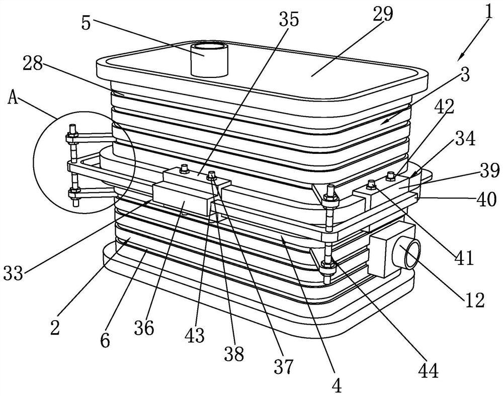
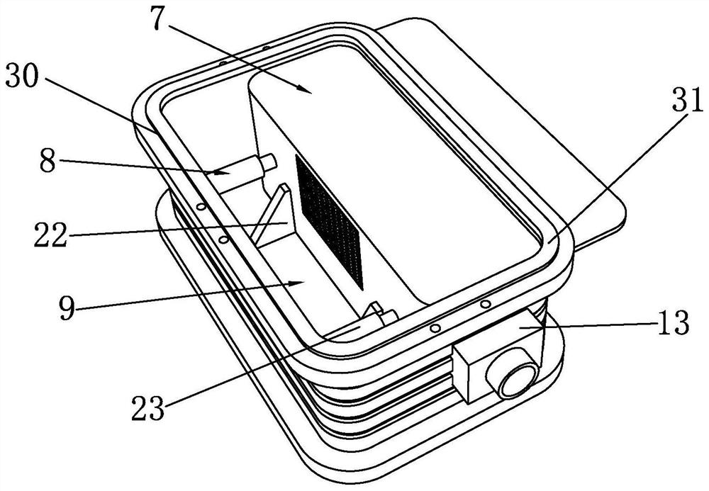
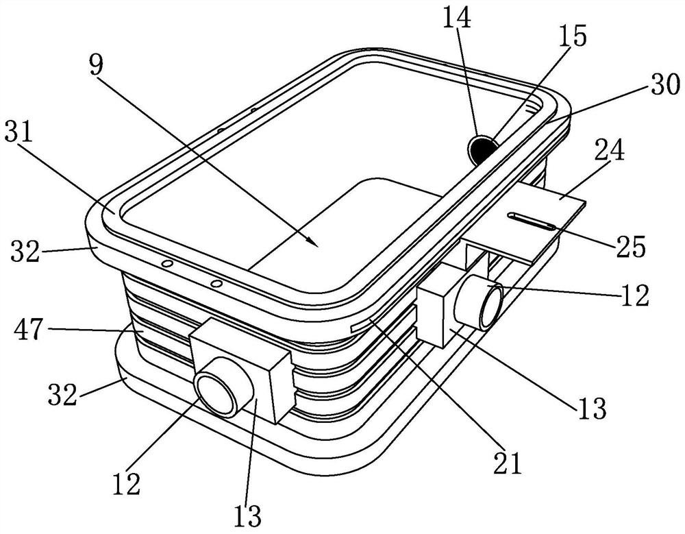
[0039] Such as Figure 1 to Figure 6 As shown, the rainwater automatic lifting device in the underground rainwater pipeline of the present invention includes a body 1, a collection mechanism 2 is provided at the bottom of the body 1, and a storage component 3 is superimposed on the top of the collection mechanism 2. The connection between the collection mechanism 2 and the storage component 3 A reinforcement component 4 is connected between them, a drainage pipe 5 is provided on the top of the storage component 3, and a drainage pump is provided in the drainage pipe 5. The collection mechanism 2 includes a collection box 6, a filter assembly 7 and an adjustment assembly 8. The collection box 6 is provided with a collection Cavity 9, filter assembly 7 and adjustment assembly 8 are all set in the collection chamber 9, the filter assembly 7 is movably connected to the adjustment assembly 8, the filter assembly 7 separates the collection chamber 9 into a water inlet tank 10 and a d...


PUM


Abstract

The invention discloses an automatic rainwater lifting device in an underground rainwater pipeline and a construction method. The method comprises the following steps of a, preparation before construction; b, assembling a collecting mechanism; c, stacking the collecting mechanism and a storage assembly; d, placing a horizontal base; and e, mounting. According to the automatic rainwater lifting device, the rainwater lifting device is arranged at the joint of the underground rainwater pipeline, so that rainwater in an underground rainwater pipeline is discharged into a water inlet groove in a collecting cavity through a water inlet pipe on the outer side of a collecting box, and the rainwater in the water inlet groove is filtered through a filtering assembly in the collecting cavity and then discharged into a drainage groove, rainwater in the drainage groove is sucked into the storage assembly through a drainage pump and then drained through the drainage pipe for centralized treatment, the rainwater in the rainwater pipeline is prevented from overflowing to a road, the safety of the road surface is guaranteed, and meanwhile it is avoided that the rainwater is accumulated in the underground rainwater pipeline for a long time and goes bad and smells.

Description

technical field [0001] The invention belongs to the technical field of rainwater lifting, and in particular relates to a rainwater automatic lifting device and a construction method in an underground rainwater pipeline. Background technique [0002] Rain refers to the weather phenomenon in which water vapor condensed in the atmosphere falls to the earth's surface in various ways. Almost all the water vapor in the atmosphere is concentrated in the troposphere. The higher the temperature, the more water vapor the atmosphere can hold, and vice versa. At a certain temperature, when the air cannot hold more water vapor, it is called saturated air. When the water vapor in the saturated air matches the temperature, condensation does not occur, but when the air is supersaturated, excess water vapor is produced and condensation occurs. [0003] When it rains, a large amount of rainwater falls on the road, and the rainwater falls into the underground rainwater pipe through the rainw...

Claims


Application Information

Patent Timeline
IPC IPC(8): E03F5/22E03F5/10E03F5/14B01D29/56
CPCE03F5/22E03F5/10E03F5/14B01D29/56Y02A20/20Y02A20/108
Inventor 毛建生毛鑫昕姜伟杨玉泉姚金兰
Owner ZHEJIANG TONGJI VOCATIONAL COLLEGE OF SCI & TECH
Why Eureka
Eureka Blog
Learn More