
Energy-saving micro water pump

A miniature water pump, energy-saving technology, applied in the direction of pumps, pump components, non-variable-capacity pumps, etc., can solve the problems of winding on the booster vanes and hindering the rotation of booster vanes.

Inactive Publication Date: 2021-06-25
TAIZHOU LEYAN AUTOMATION SCIEN-TECH CO LTD
View PDF0 Cites 0 Cited by
  • Summary
  • Abstract
  • Description
  • Claims
  • Application Information

AI Technical Summary

Problems solved by technology

[0003] Because there are many aquatic plants in the stream, if the energy-saving micro-water pump is placed outdoors to extract water from the stream, it is easy for the long strips of aquatic plants in the stream to follow the water flow into the interior of the energy-saving micro-water pump, so that the long strips of aquatic plants will be entangled. On the booster blade, if it is not cleaned in time, the long-term accumulation will cause the rotation of the booster blade to be blocked

Method used


Image

  • Energy-saving micro water pump
  • Energy-saving micro water pump
  • Energy-saving micro water pump

Examples


Embodiment 1

[0026] For example figure 1 -example Figure 5 Shown:

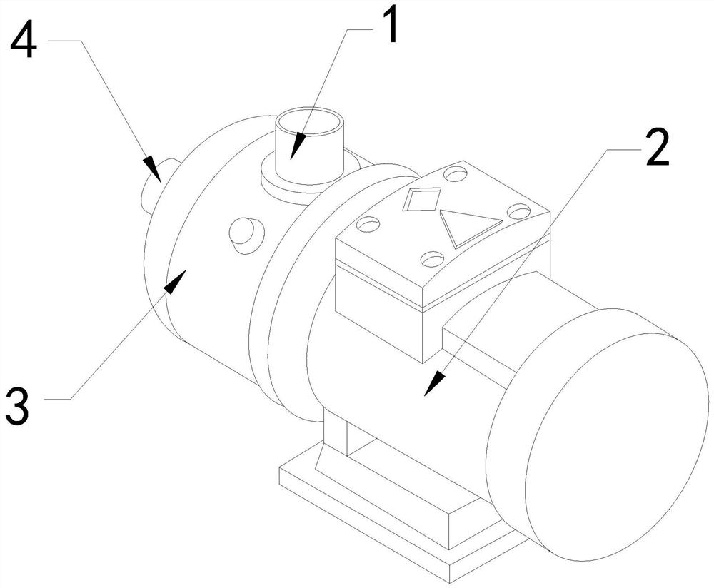
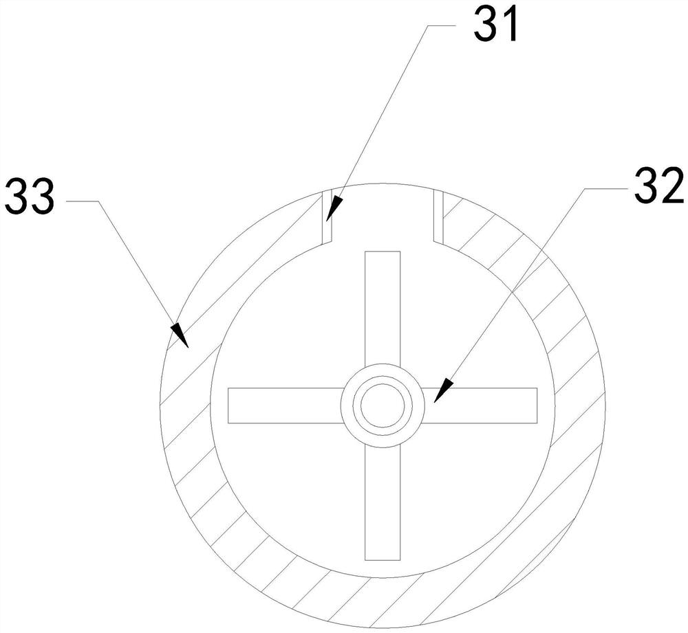
[0027] The invention provides an energy-saving micro water pump, the structure of which includes a water outlet pipe 1, a driving end 2, a booster mechanism 3, and a water inlet pipe 4. 4 installed on the upper end of the supercharging mechanism 3, the supercharging mechanism 3 and the driving end 2 are an integrated structure; the supercharging mechanism 3 includes a drain port 31, a booster roller 32, and an outer frame 33 31 and the outer frame 33 are integral structures, and the booster roller 32 is movably engaged with the outer frame 33 .

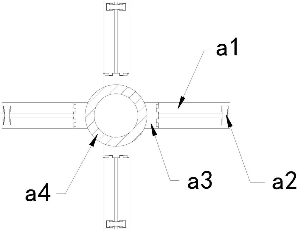
[0028] Wherein, the booster roller 32 includes an outer sliding plate a1, a middle connecting rod a2, a guide frame a3, and a middle ring a4. Between the outer slides a1, the pedestal a3 is connected to the outer surface of the middle ring a4. There are eight outer slides a1, and two of them form a group and are evenly distributed in a circle outside the four pedestals a3. Th...

Embodiment 2

[0034] For example Figure 6 -example Figure 8 Shown:

[0035] Wherein, the blade b4 includes an outer contact ball c1, a contact frame c2, a rear plate c3, and a resilient piece c4. The outer contact ball c1 is installed in the inner position of the contact frame c2. The right side of the rear panel c3 is connected, and the outer touch ball c1 is provided with four, and two of them are evenly distributed symmetrically at the upper and lower ends of the contact frame c2, and are squeezed by the object on the contact frame c2 , the contact frame c2 can be shrunk inward, so that an airflow can be generated to push the outer contact ball c1 outward.

[0036] Wherein, the outer touch ball c1 includes a ring body c11, an extruding block c12, a water diversion chamber c13, and a fixed block c14. The position of the inner wall of c13, the water diversion cavity c13 is embedded between the inner side of the ring body c11 and the outer surface of the fixed block c14, the ring body ...


PUM


Abstract

The invention discloses an energy-saving micro water pump. The pump structurally comprises a water outlet pipe, a driving end, a pressurizing mechanism and a water inlet pipe, the water outlet pipe is fixedly embedded at the upper end position of the pressurizing mechanism, the water inlet pipe is installed at the upper end position of the pressurizing mechanism, and the pressurizing mechanism and the driving end are of an integrated structure. Through the inertia force generated by outward extending of an outward extending block, a plate body can rotate along a bottom block, so that blades can extend outwards along the plate body, the blades can cut off long-strip aquatic plants along with rotation of the plate body, the situation that the long-strip aquatic plants in a stream can be wound on the blades is effectively avoided, water flow can be guided into a water diversion cavity through holes in a ring body, through throwing force generated by rolling of an outer contact ball, an extrusion block can extend outwards along the water diversion cavity, so that the extrusion block can extrude water in the water diversion cavity outwards, and the water can wash away the long-strip aquatic plants adhered to the outer surface of the outer contact ball.

Description

technical field [0001] The invention relates to the field of water pumps, in particular to an energy-saving miniature water pump. Background technique [0002] The energy-saving micro-water pump is mainly used for cross-regional transmission of water flow. The water flow is drawn in through the water inlet pipe, and then the water is introduced into the inside of the water outlet pipe through the high-speed rotation of the internal booster blade, and finally the water flow is exported through the water outlet pipe for cross-regional transfer. Regional transmission, based on the above description, the inventors found that an existing energy-saving micro-pump mainly has the following deficiencies, for example: [0003] Because there are many aquatic plants in the stream, if the energy-saving micro-water pump is placed outdoors to extract water from the stream, it is easy for the long strips of aquatic plants in the stream to follow the water flow into the interior of the energ...

Claims


Application Information

Patent Timeline
Patent Type & Authority Applications(China)
IPC IPC(8): F04D7/04F04D29/00F04D29/70B02C18/14
CPCF04D7/045F04D29/007F04D29/708B02C18/14
Inventor 闫保健
Owner TAIZHOU LEYAN AUTOMATION SCIEN-TECH CO LTD
Learn More