Rotor blade component, method for producing same, and wind turbine

A technology for rotor blades and components, applied in the field of rotor blade components, can solve problems such as thickness reduction, and achieve the effect of saving materials and weight

Active Publication Date: 2021-06-25
西门子歌美飒可再生能源服务股份有限公司
View PDF2 Cites 0 Cited by
  • Summary
  • Abstract
  • Description
  • Claims
  • Application Information

AI Technical Summary

Problems solved by technology

But what is difficult for technical reasons in this case is to reduce the thickness at the end of the layer to zero when chamfering

Method used


Image

  • Rotor blade component, method for producing same, and wind turbine
  • Rotor blade component, method for producing same, and wind turbine
  • Rotor blade component, method for producing same, and wind turbine

Examples


Embodiment Construction

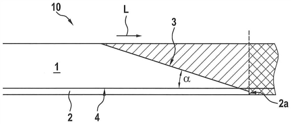
[0032] figure 1 A side view of an example of an end portion of a layer system 10 comprising a first material, for example a first layer 1 of carbon fibers, and a second material, for example a second layer 2 of glass fibers, is shown. In this case, the second layer 2 has a lower modulus of elasticity in the longitudinal direction L than the first layer 1 . Furthermore, the second layer is designed to be significantly thinner than the first layer, in particular substantially 10 times thinner.

[0033] The layer system 10 has a chamfered end with an end face 3 which is inclined at a chamfer angle α relative to the contact surface 4 between the first and second layers 1 , 2 . In this case, the end face 4 extends over the entire thickness of the first layer 1 and over at least a part of the second layer 2, so that in the side view shown the first layer 1 runs sharply closer at a chamfer angle α, while the second layer 1 The layer 2 has a blunt end, ie an end with an end side 2 a...


PUM


Abstract

The invention relates to a method for producing a rotor blade component for a rotor blade of a wind turbine, to a rotor blade component, and to a wind turbine having such a rotor blade component. A layer system (10), consisting of a first layer (1) made of a first material and a second layer (2) made of a second material, is produced. The second material has a lower modulus of elasticity than the first material, and at least part of the second layer (2) runs along the first layer (1). The layer system (10) is chamfered, at least at one end, by means of at least one cutting method in such a way that the second layer (2) protrudes beyond the first layer (1) at the at least one end of the layer system (10). Furthermore, the layer system (10) is joined to at least one other such layer system (10) to form the rotor blade component.

Description

technical field [0001] The invention relates to a method for producing a rotor blade part, in particular a rotor blade strip, for producing a rotor blade for a wind energy installation, a rotor blade part and a wind energy installation having such a rotor blade part. Background technique [0002] Rotor blades for wind energy installations are usually assembled from two rotor blade shells which are manufactured separately from one another. In this case one or more bands can be provided inside the rotor blade, which extend substantially along the longitudinal axis of the rotor blade from the rotor blade root to the rotor blade tip and additionally bring stability or influence the elastic properties of the rotor blade . [0003] Such belts are usually produced by using a pultrusion method (pultrusion method), in which, for example, individual pultruded layers made of fiber material such as carbon fibers are connected to each other in layers to form a belt. In order to reduce ...

Claims


Application Information

Patent Timeline
IPC IPC(8): B29C65/48B29C65/00B32B37/14B32B38/00F03D1/06B29L31/08
CPCB29C65/48B29C66/0224B29C66/02241B29C66/02245B29C66/1122B29C66/346B29C66/45B29C66/7212B29C66/72141B29C66/723B29C66/7315B29L2031/085B32B37/144B32B38/105B32B2603/00F03D1/0675Y02E10/72Y02P70/50B29K2307/04B29K2309/08F03D13/10B29C66/122B29C66/636B29D99/0025F05B2280/50F05B2280/6003
Inventor 恩诺·艾布
Owner 西门子歌美飒可再生能源服务股份有限公司
Why Eureka
Try Eureka