Busbar system

A busbar and segment technology, applied in the direction of engines, wind power generation, electrical components, etc., can solve problems such as thermal blockage, busbar component size and ventilation restrictions of the system, and achieve low cost, weight and material savings.

Active Publication Date: 2013-10-30
SIEMENS AG
View PDF5 Cites 0 Cited by
  • Summary
  • Abstract
  • Description
  • Claims
  • Application Information

AI Technical Summary

Problems solved by technology

[0002] The housings and busbars of previous busbar systems form a functional unit, which creates restrictions in terms of the dimensions of the busbar elements and the ventilation of the system
Especially when transferring energy over long vertical paths, such as in tall buildings or wind energy installations, thermal blockages can occur in the upper area of ​​the installed busbar system due to restricted ventilation or convection inside the busbar box

Method used


Image

  • Busbar system
  • Busbar system
  • Busbar system

Examples


Embodiment Construction

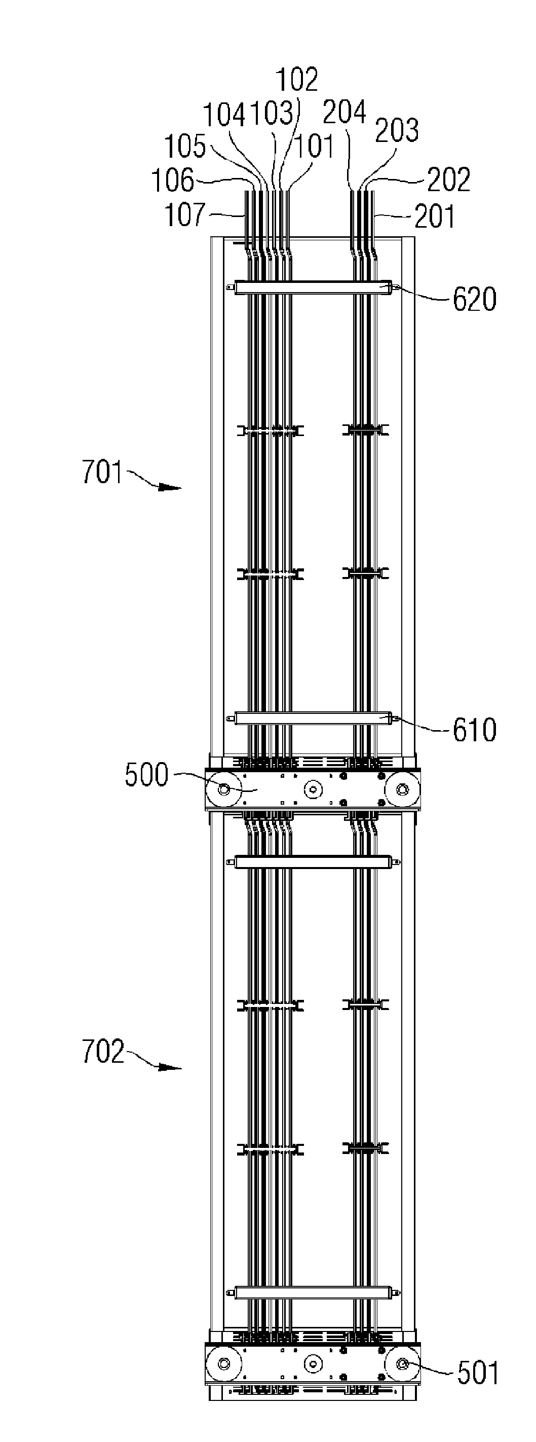
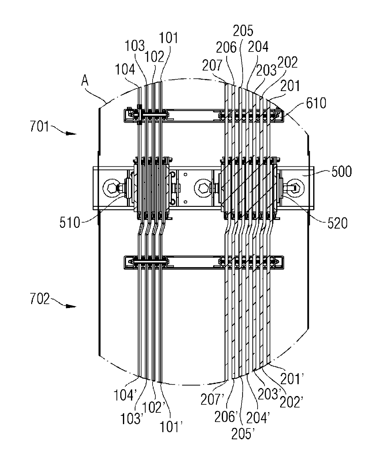
[0027] exist Figure 1A A busbar system for conveying electrical energy is shown in , which is shown in a first projection projected onto a plan view of the busbar system. The busbar system comprises a first segment 701 and a second segment 702 . The segments 701, 702 respectively include first bus bars 101, 102, 103, 104, 105, 106, 107 with a first cross-section and holders 500, 501, wherein the bus bars of each segment 701, 702 They are held by corresponding holders 500 , 501 and are electrically connected to each other through connection mechanisms 510 , 520 . according to Figure 1A , the holder 500 is assigned to the first segment 701 and the holder 501 is assigned to the second segment 702 . The connecting means 510, 520 connect the respective first bus bars 101, 102, 103, 104, 105, 106, 107 of the first and second segments.

[0028] The busbars of the busbar system according to the invention are elongated in the direction of current flow. according to Figure 1A , wh...


PUM


Abstract

The invention relates to busbars having different cross sections for a busbar system with a common protection and / or neutral conductor for the transport of electrical energy, wherein the busbar system comprises at least one first segment and a second segment, the segments having each at least one first busbar with a first cross-sectional area, at least a second busbar with a second cross-sectional area, a holding element and at least one connection. According to the invention, the busbars of the segments are held by the respective holding element and are electrically connected to each other via the at least one connection, and a busbar from either the first busbars or second busbars serves as a common protection conductor (PE) and / or as a common neutral conductor.

Description

Background technique [0001] The power distribution system can be configured as a busbar system. Busbar systems are used to transport and distribute electrical energy. Typical tasks of busbar systems are, for example, the connection of transformers via master distributors to slave distributors or the supply of large consumers. Busbar systems are likewise used in wind power installations to guide the electrical current generated in the tower top of the generator to the tower bottom. The busbars of a busbar system are typically housed in a busbar box which prevents unwanted electrical contact between the busbars and the surrounding environment. In this case, the busbar box is dimensioned in such a way that on the one hand a distance is maintained to prevent unwanted electrical contact and on the other hand the busbars inside the busbar box are cooled by natural and / or forced convection. [0002] The housings and busbars of previous busbar systems form a functional unit, which ...

Claims


Application Information

Patent Timeline
IPC IPC(8): H02B1/20H02G5/00
CPCH02G5/06Y02E10/722H02G5/025H02G3/0493H02G5/007F03D11/0066F03D80/85Y02E10/72H02B1/202H02B1/565
Inventor F.阿勒费尔德F.贝特尔斯
Owner SIEMENS AG
Why Eureka
Try Eureka