Vertical storage rack for cold storage units

a vertical storage and storage rack technology, applied in the field of storage racks, can solve the problems of high labor intensity and high time-consuming in the manufacturing process of these conventional storage racks, and achieve the effect of saving material and weight of storage racks and simplifying the manufacturing of storage racks

Inactive Publication Date: 2013-09-12
THERMO FISHER SCI ASHEVILLE
View PDF8 Cites 23 Cited by
  • Summary
  • Abstract
  • Description
  • Claims
  • Application Information

AI Technical Summary

Benefits of technology

[0006]In one embodiment according to the present invention, a storage rack for holding storage boxes within a cold storage unit includes a rack body including a rear wall and first and second opposed sidewalls extending from the rear wall. A plurality of shelves is defined by a series of first lips punched from the first sidewall and a series of second lips punched from the second sidewall. The first and second lips are bent towards each other and spaced from each other. The storage rack also includes a handle supported by the rack body and configured to support the storage rack during movement into and out of the cold storage unit. Forming the plurality of shelves by punching and bending lips from the first and second sidewalls saves material and weight of the storage rack while simplifying manufacturing of the storage rack.

Problems solved by technology

The manufacturing process for these conventional storage racks is highly time-consuming and requires skill-intensive labor.
Additionally, when fully loaded with storage boxes filled with vials, each storage rack defines a relatively heavy weight that may be difficult to lift into and out of the opening at the top of the tank.

Method used


Image

  • Vertical storage rack for cold storage units
  • Vertical storage rack for cold storage units
  • Vertical storage rack for cold storage units

Examples


Embodiment Construction

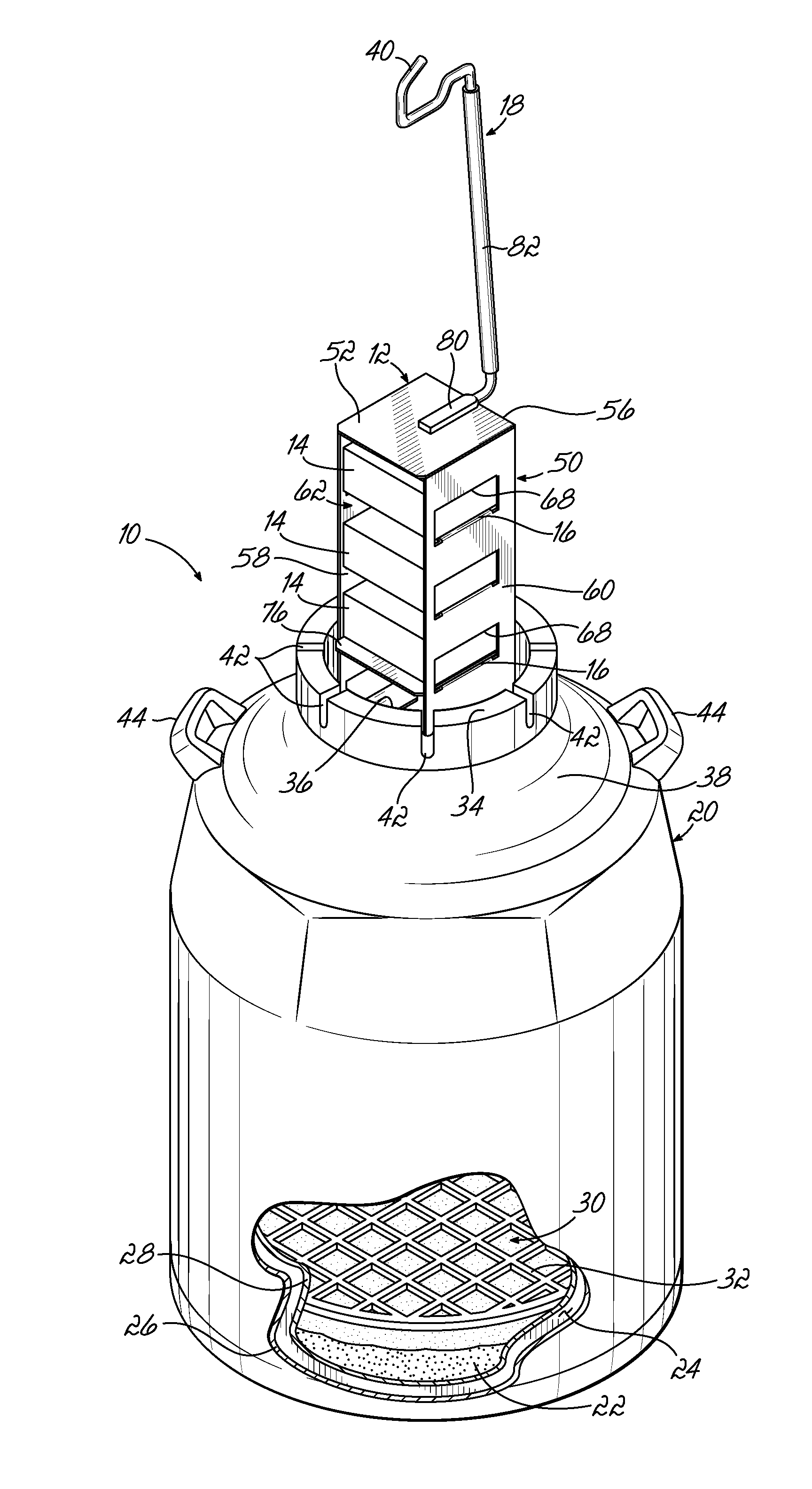
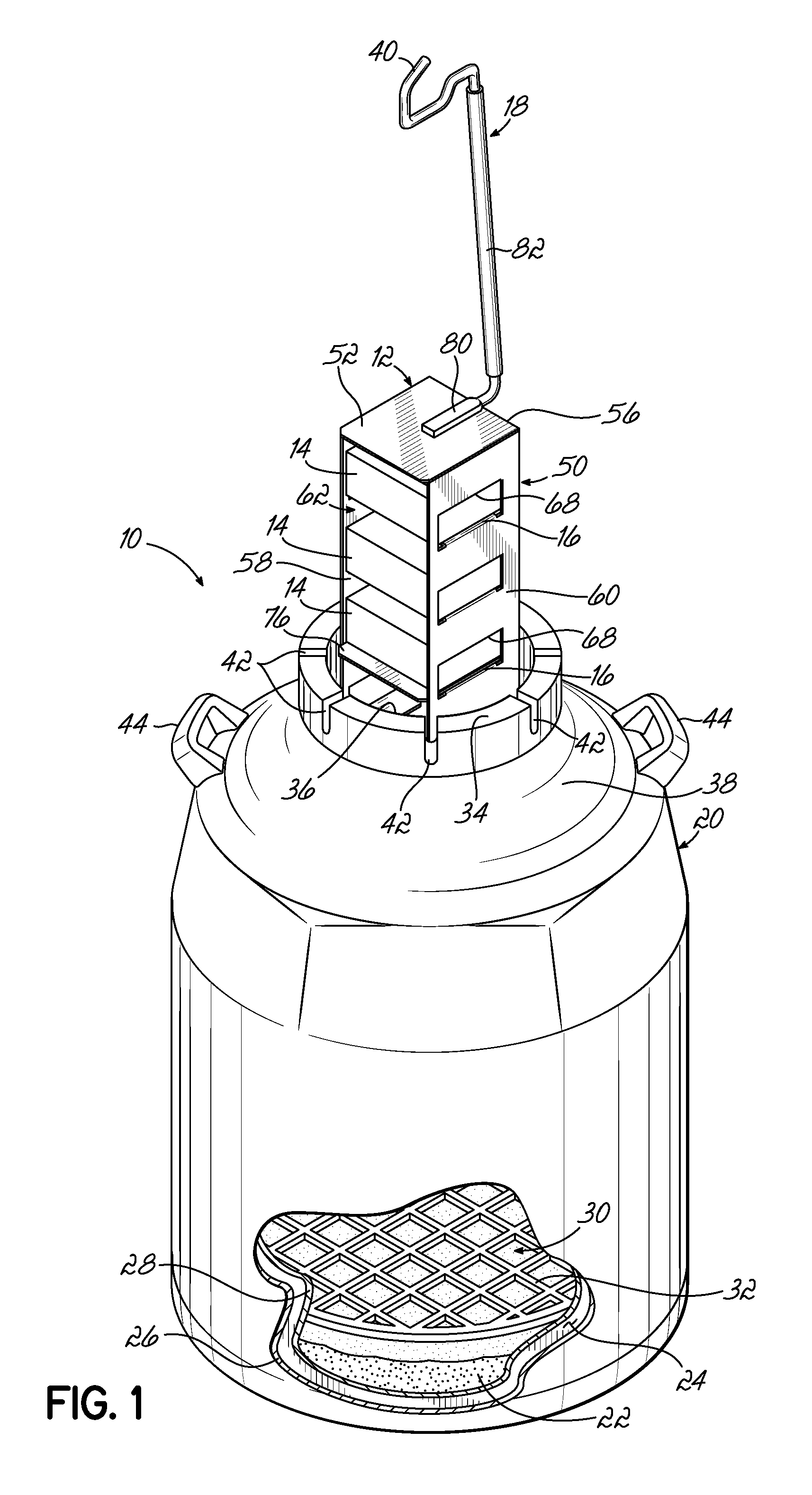
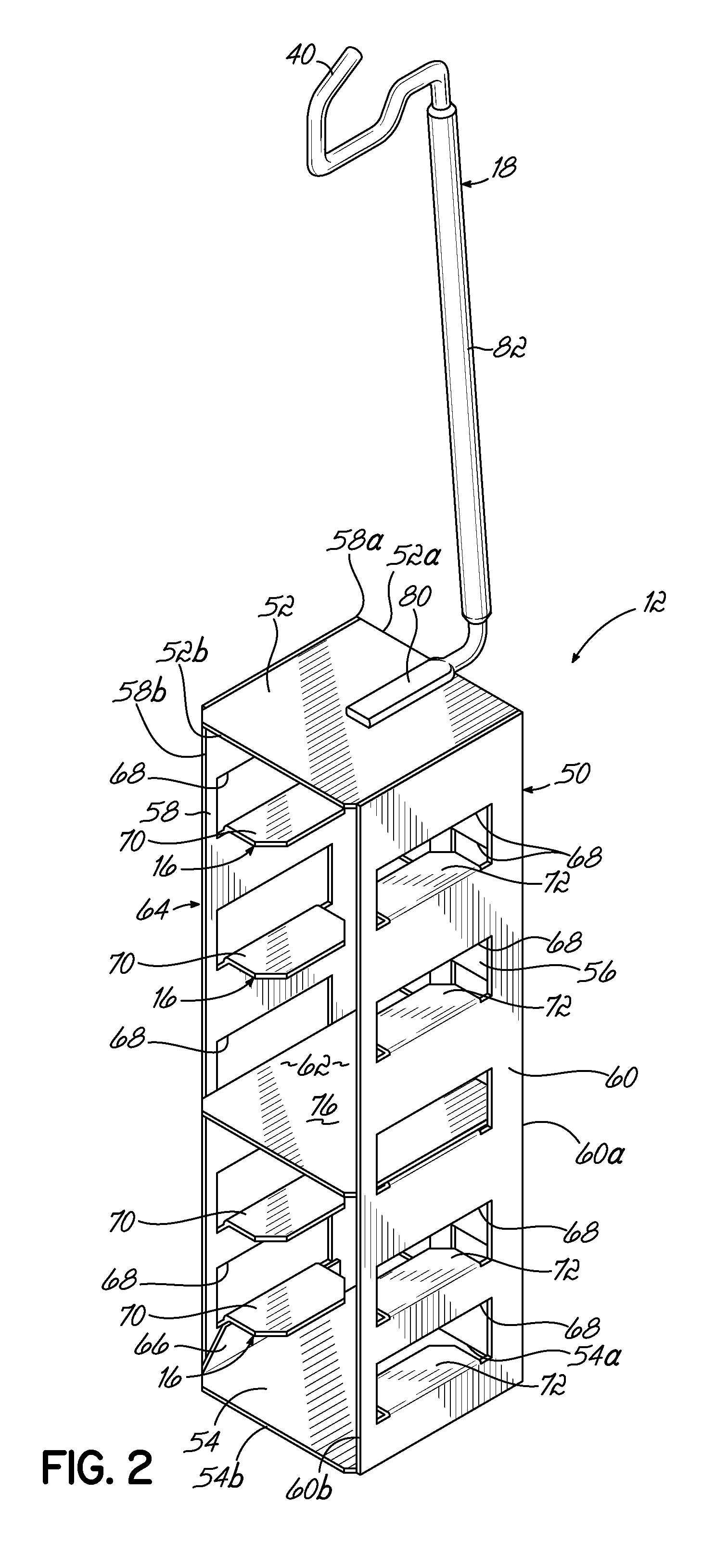
[0019]With reference to the figures, and more specifically to FIGS. 1 through 4, a liquid nitrogen cryogenic dewar 10 including an exemplary vertical storage rack 12 according to one embodiment of the present invention is illustrated. Although the term “cryogenic dewar” is used throughout the specification when referring to this embodiment of the invention, it will be understood that this and other embodiments of the vertical storage rack 12 disclosed herein may be used with any type of refrigerator, freezer and cryogenic vessel (collectively referred to hereafter as “cold storage units”), such as, in one example, a chest freezer. In addition, it will be understood that the cryogenic dewar 10 may be cooled by liquid nitrogen, by a mechanical cooling circuit, or by any other known cooling methods. The vertical storage rack 12 is shaped and sized to receive a column or stack of cryogenic storage boxes 14 (alternatively a column or stack of “micro plates”) as shown in FIG. 1. The stora...


PUM

PropertyMeasurementUnit
temperatureaaaaaaaaaa
storage temperatureaaaaaaaaaa

Abstract

A cold storage unit such as a cryogenic dewar includes a tank with an opening, a storage space communicating with the opening, and a pool for liquid nitrogen positioned adjacent the storage space. The storage space receives a plurality of storage racks, each including a rack body with a rear wall and first and second sidewalls extending from the rear wall. The storage rack also includes a plurality of shelves, each shelf defined by a first lip punched from the first sidewall and a second lip punched from the second sidewall, the first and second lips being bent towards one another and spaced from one another. The shelves minimize the material and weight used in manufacturing the storage rack. Additionally, the storage rack is assembled with minimal spot welding required.

Description

FIELD OF THE INVENTION[0001]The present invention relates generally to storage racks and, more particularly, to storage racks configured for use in cold storage units such as cryogenic dewars for storing samples at about −180° C., or lower.BACKGROUND OF THE INVENTION[0002]Cold storage units such as freezers and dewars are used for various purposes, including the storage of biological samples over short and long periods of time. For example, biological materials for transplantation such as blood, tissue, or plasma may require storage for short periods of time before use. In another example, biological cells such as DNA samples may be stored for longer periods of time. Conventional cold storage units may be cooled by mechanical cooling circuits or by liquid nitrogen (“LN2”).[0003]In a known cold storage unit referred to as a LN2 cryogenic dewar, the dewar includes a tank having a vacuum-insulated shell enclosing a pool of liquid nitrogen and a storage space located above the pool of l...

Claims


Application Information

Patent Timeline
Patent Type & Authority Applications(United States)
IPC IPC(8): F17C3/00B21D31/00B23P11/00F25D25/02
CPCB21D53/00A01N1/0257Y10T29/49968Y10T29/49826A01N1/0268
Inventor WARD, DENNIS D.MCDOUGLE, JAMES O.
Owner THERMO FISHER SCI ASHEVILLE
Why Eureka
Try Eureka