Cardiovascular surgery tray with lifting height convenient to adjust
A technology for adjusting lifting and cardiovascular, which is applied in the fields of surgery, medical science, surgical equipment, etc., and can solve problems such as troublesome and inconvenient access to surgical instruments
- Summary
- Abstract
- Description
- Claims
- Application Information
AI Technical Summary
Problems solved by technology
Method used
Image
Examples
Embodiment 1
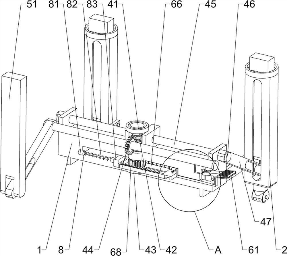
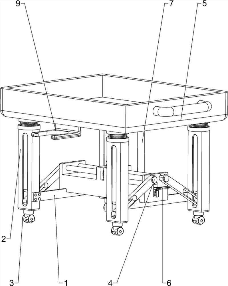
[0026] A tray for cardiovascular surgery that can be easily adjusted in lifting height, such as Figure 1-Figure 3 As shown, it includes an I-shaped support 1, a support column 2, a universal wheel 3, a drive mechanism 4 and a lifting platform mechanism 5, and the four ends of the I-shaped support 1 are fixedly connected with a support column 2, and the bottom end of the support column 2 is equipped with a Universal wheel 3, sliding type is provided with lifting platform mechanism 5 between four support columns 2, and I-shaped support 1 is provided with driving mechanism 4, and driving mechanism 4 is connected with lifting platform mechanism 5.
[0027] The driving mechanism 4 includes a driving knob 41, a driving worm 42, a positioning cylinder 43, a driving worm gear 44, a transmission shaft 45, a limit block 46 and a swing lever 47, and the upper front side of the I-shaped support 1 and the rear side all rotate. There is a drive shaft 45 in the transmission shaft 45, and a ...
Embodiment 2
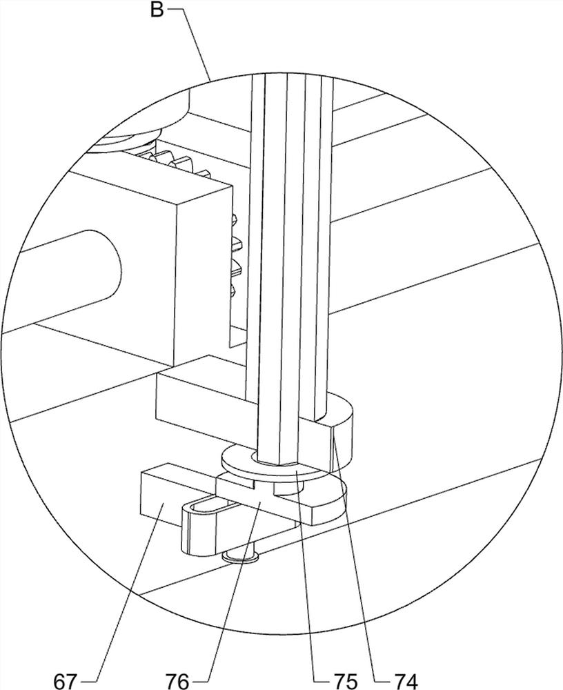
[0033] On the basis of Example 1, such as figure 1 , figure 2 , image 3 , Figure 5 and Figure 6 As shown, also include lifting auxiliary mechanism 6, and lifting auxiliary mechanism 6 includes force pedal 61, return spring 62, transmission link 63, driving frame 64, positioning lock 65, spring ratchet 66, reversing column 67 and Gear 68, I-shaped bracket 1 right side middle part front side sliding type is connected with transmission connecting rod 63, and transmission connecting rod 63 left end sliding type is provided with driving frame 64, and driving frame 64 is positioned at I-shaped bracket 1 inside, and driving frame 64 top right fronts are fixedly connected with two positioning locks 65, and the positioning locks 65 cooperate with the groove of the transmission connecting rod 63, and the rotary type embedded in the upper front side of the right side of the I-shaped support 1 is connected with a force pedal 61 , the bottom end of the stressed pedal 61 is slidingl...
Embodiment 3
[0038] On the basis of embodiment 1 and embodiment 2, such as figure 1 , figure 2 and Figure 4 As shown, it also includes an auxiliary mechanism 8, which includes a spring seat 81, an auxiliary spring 82 and a rubber push plate 83, and the left side of the I-shaped support 1 is slidingly placed with a rubber push plate 83, and the rubber push plate Plate 83 is positioned at the left side of drive frame 64 and is in contact with it, and rubber push plate 83 is fixedly connected with spring seat 81 symmetrically front and rear on the left side, and spring seat 81 is also symmetrically fixed at front and back at left side in the I-shaped support 1, two on each side. Actuating springs 82 are connected between the spring seats 81 .
[0039] Also include garbage storage mechanism 9, garbage storage mechanism 9 includes spring cover plate 91, storage rack 92 and spring dead bolt 93, storage platform 55 outer bottom left front part is fixedly connected with storage rack 92, left a...
PUM
 Abstract
Description
Claims
Application Information
 - R&D Engineer
- R&D Manager
- IP Professional
- Industry Leading Data Capabilities
- Powerful AI technology
- Patent DNA Extraction
Browse by: Latest US Patents, China's latest patents, Technical Efficacy Thesaurus, Application Domain, Technology Topic, Popular Technical Reports.
© 2024 PatSnap. All rights reserved.Legal|Privacy policy|Modern Slavery Act Transparency Statement|Sitemap|About US| Contact US: help@patsnap.com


