
A Thrust Balanced Structure

A technology of thrust balance and gas pipe, applied in the direction of machines/engines, blade support components, mechanical equipment, etc., can solve the problems of increasing unit loss, poor axial thrust bearing capacity, limiting the use of electromagnetic bearings and air bearings, etc. Achieve the effects of reducing friction loss, increasing safety, and strong ability to change working conditions

Active Publication Date: 2022-01-14
DONGFANG TURBINE CO LTD
View PDF15 Cites 0 Cited by
  • Summary
  • Abstract
  • Description
  • Claims
  • Application Information

AI Technical Summary

Problems solved by technology

In the field of high-speed rotating turbines, more and more equipment began to use electromagnetic bearings and air bearings with low noise and low loss as the thrust bearings of the unit, but the common problem faced by electromagnetic bearings and air bearings is their axial thrust. The bearing capacity is poor. Even if the commonly used rotor balance plate structure is adopted, it can only reduce the thrust value of the unit under rated working conditions to a certain extent, and cannot control the thrust value of the unit under variable or full working conditions at a relatively low level. In the low range, this greatly limits the application of electromagnetic bearings and air bearings in high-pressure, high-speed, and high-power units. At the same time, if oil bearings are used, the loss of the unit will increase

Method used


Image

  • A Thrust Balanced Structure
  • A Thrust Balanced Structure
  • A Thrust Balanced Structure

Examples


Embodiment 1

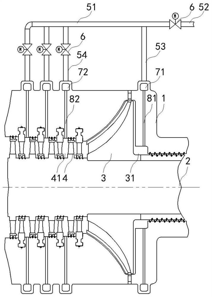
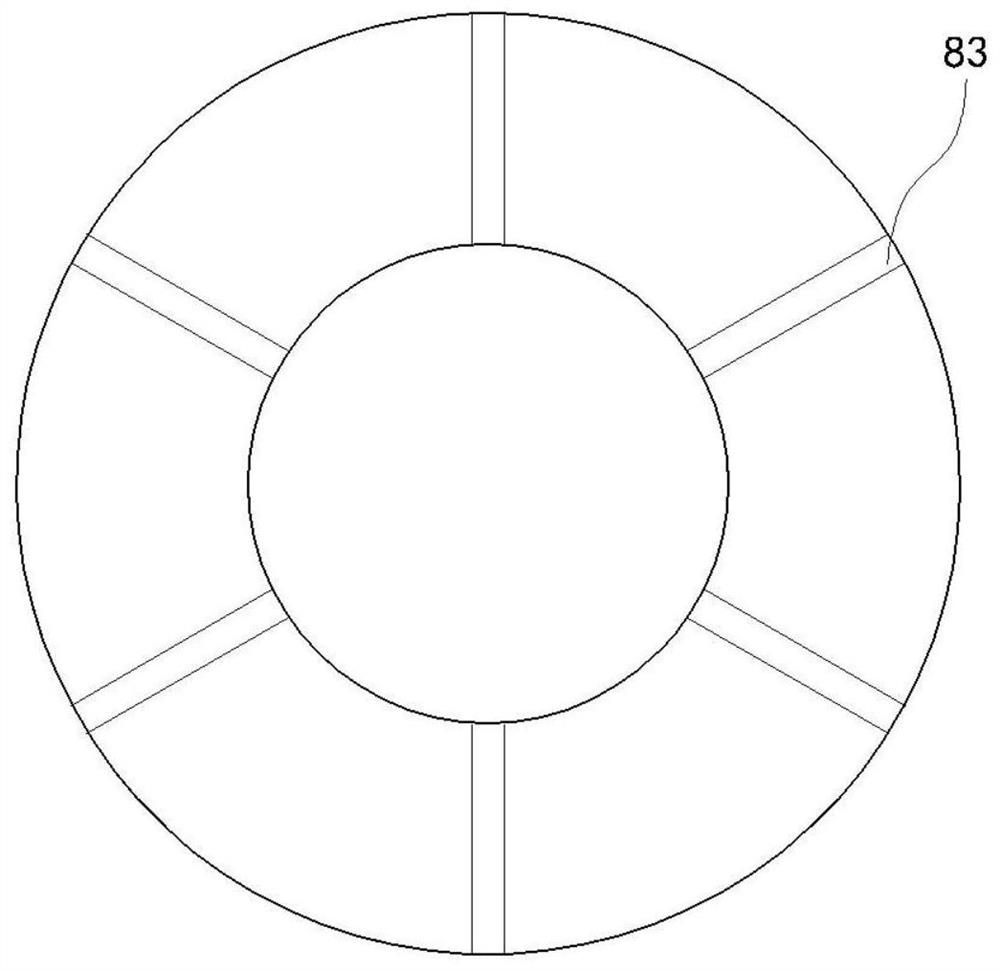
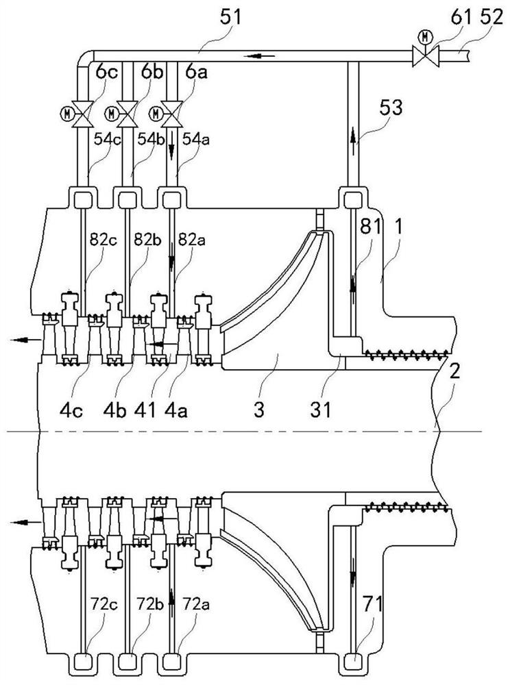
[0040] Such as Figure 1-2 As shown, a thrust balance structure of this embodiment includes a cylinder 1, a rotor 2 is arranged in the cylinder 1, and a centripetal impeller 3, a first movable blade cascade 4a, a second movable blade cascade 4b and a third movable blade cascade are arranged in sequence on the rotor 2 moving blade cascade 4c;

[0041] The air inlet pipe 52, the impeller air pipe 53, the first cascade air pipe 54a, the second cascade air pipe 54b and the third cascade air pipe 54c are connected through the air pipe 51; The regulating valve 61, the first electric regulating valve 6a, the second electric regulating valve 6b, and the third electric regulating valve 6c are respectively arranged on the first cascade air pipe 54a, the second cascade air pipe 54b, and the third cascade air pipe 54c;

[0042] The impeller air pipe 53, the first cascade air pipe 54a, the second cascade air pipe 54b, and the third cascade air pipe 54c are respectively connected with the ...


PUM


Abstract

The invention discloses a thrust balance structure, which comprises a cylinder, a rotor is arranged in the cylinder, and a centripetal impeller and a plurality of groups of movable blade cascades are sequentially arranged on the rotor; the air pipe includes a connecting air pipe, an air inlet pipe, an impeller air pipe and a plurality of blade cascade air pipes, and The air pipe, impeller air pipe and multiple cascade air pipes are connected through the connecting air pipe; the electric control valve is respectively arranged on the air inlet pipe and the cascade air pipe; On the cylinder, it communicates with the impeller air pipe and a plurality of cascade air pipes respectively; the porous passage includes the impeller passage and a plurality of cascade passages, and the porous passage includes a plurality of through holes arranged in the circumferential direction; one end of the impeller passage passes through the ring cavity and the impeller The gas pipe is connected, and the other end is connected to the back chamber of the centripetal impeller; one end of the cascade channel is respectively connected to the air pipe of the cascade through the annular cavity, and the other end is connected to the rear chamber of the moving blade cascade respectively. The thrust balance structure of the present invention can control the thrust value of the rotating parts of the unit in real time.

Description

technical field [0001] The invention relates to a thrust balance structure, which belongs to the technical field of energy power generation. Background technique [0002] The rotating parts of the turbine unit will always generate a certain axial thrust under the action of the inlet and exhaust pressure difference. In order to balance this part of the thrust, it is often necessary to configure a thrust bearing. The power consumption is also greater. In the field of high-speed rotating turbines, more and more equipment began to use electromagnetic bearings and air bearings with low noise and low loss as the thrust bearings of the unit, but the common problem faced by electromagnetic bearings and air bearings is their axial thrust. The bearing capacity is poor. Even if the commonly used rotor balance plate structure is adopted, it can only reduce the thrust value of the unit under rated working conditions to a certain extent, and cannot control the thrust value of the unit un...

Claims


Application Information

Patent Timeline
Patent Type & Authority Patents(China)
IPC IPC(8): F01D5/02F01D5/14F01D5/16F01D25/00F01D25/16
CPCF01D25/00F01D5/027F01D25/16F01D5/141F01D5/147F01D5/16
Inventor 倪剑侯明军孙奇张晓丹范立华钱勇田瑞青
Owner DONGFANG TURBINE CO LTD
Learn More